This is a summary posting of my horizontal offset build. It combines and streamlines all of the posts I made during the build, as well as covering work done since I stopped posting.
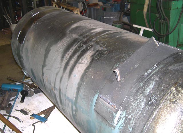
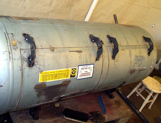
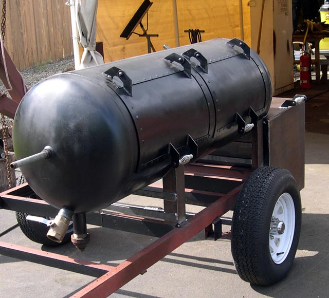
I started with an old air tank 24" diameter, 70" long and 57" between the welds. It has 3/16" wall give or take a few thou. It's a 120 gallon tank.
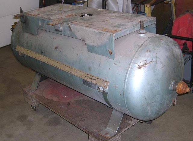
This tank has a lot of pipe ports (threaded weld-on fittings). All of these ports are either on the cylindrical part of the tank, or in the center of one of the end bells.
I cut out and patched many of these, welding in a piece of the same wall thickness as the tank. Then I sanded down the weld to blend it so it looks like there never was a threaded fitting welded in.
This build started by working on the tank. The first thing I did was to cut out and patch some of these extra ports. Here's how:
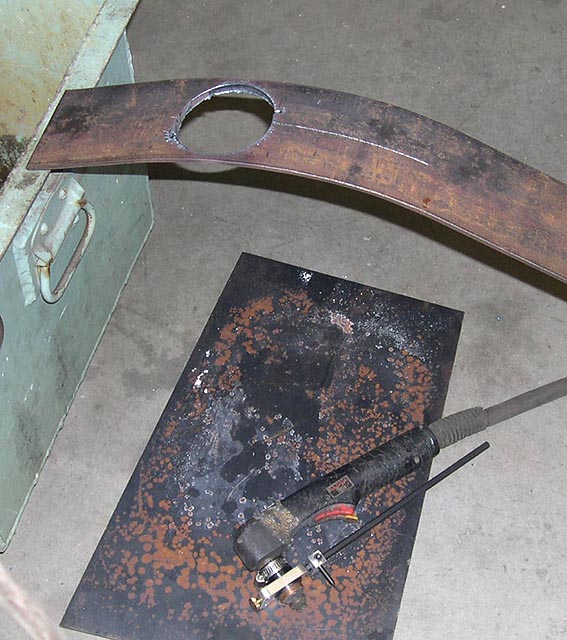
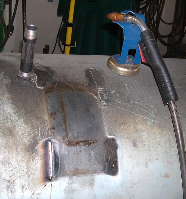
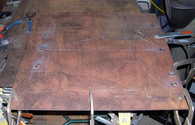
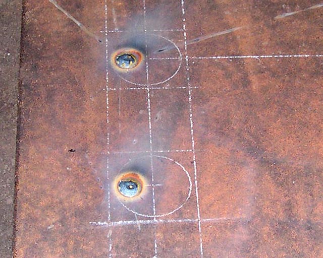
I formed some 3/16" bar to match the tank. I scribed the center of the bent stock to help with aligning the patch with the curvature of the tank, and then cut out the patch with my plasma cutter, using a circle cutting attachment:
I fit the patch using strong magnets to keep the patch from falling through:
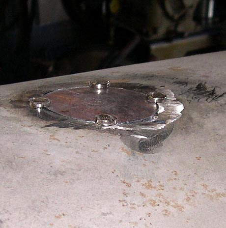
Once fit, I was able to tack, then weld in the patches. With the pipe port patches welded and sanded smooth, I cut off the tank legs and then patched some of the resulting scars:
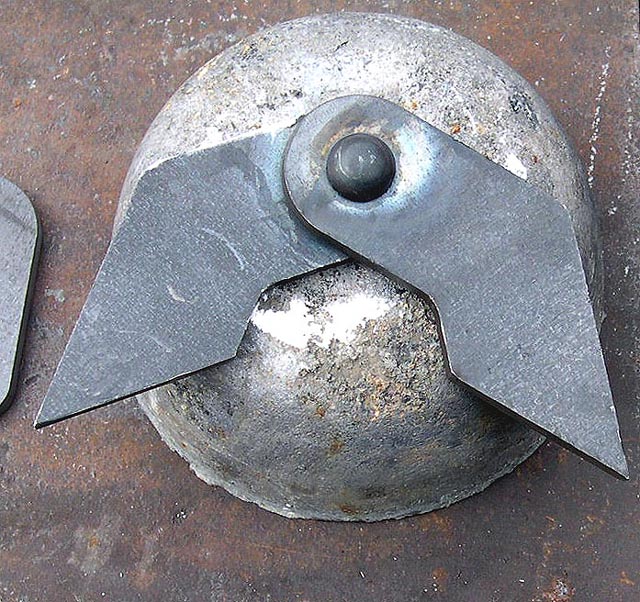
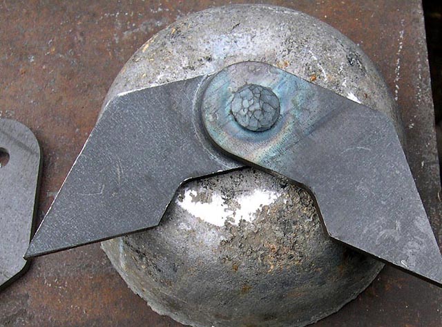
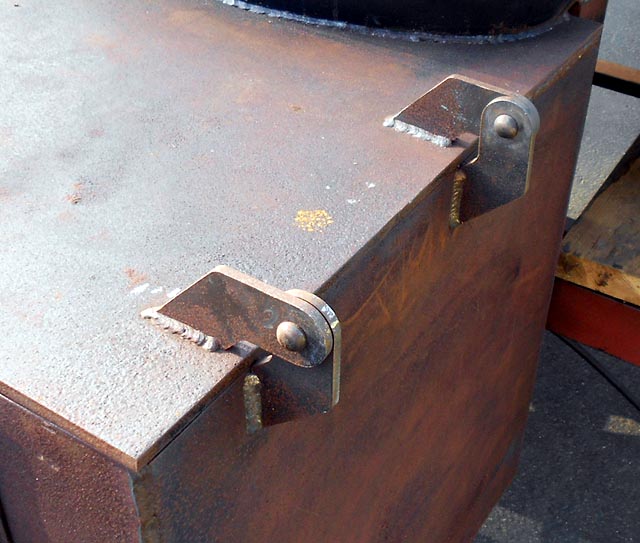
I had a buddy waterjet me some hinges.
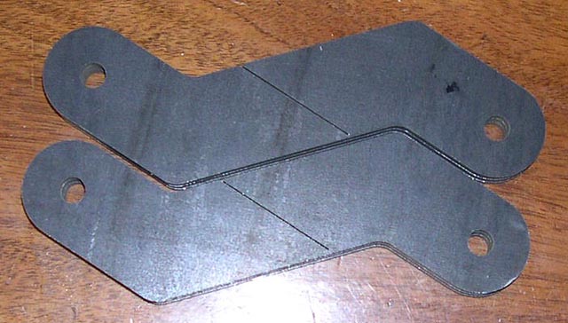
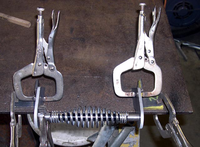
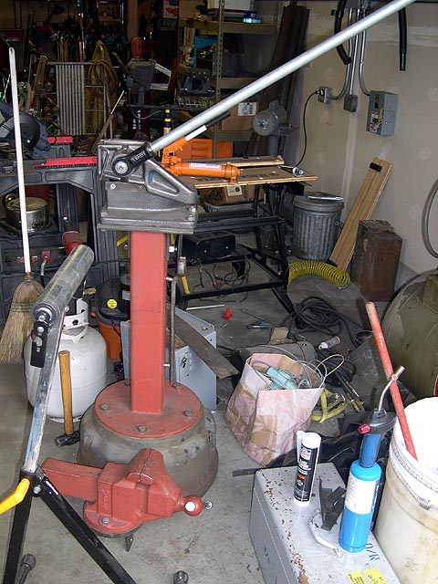
I riveted them together. I bought the rivets at R.J. Leahy (link). I used 3/8" rivets and since I had to clear 1/2" of material and wanted 9/16" stickout (1.5 rivet diameters to form the head from). I ordered 1-1/4" rivets and trimmed them to length. To do this, I clamped each rivet in a Vise-Grip and clamped the Vise-Grip in a vise, then used a cutoff wheel in an angle grinder to whack off about the right amount. To form a riveting buck (to support the factory rivet head during riveting so it doesn't deform) I hammered a rivet head into a block of lead. Then I used a very coarse file to dress the lead, which had a huge "splash" around the hole. Here's my riveting setup:
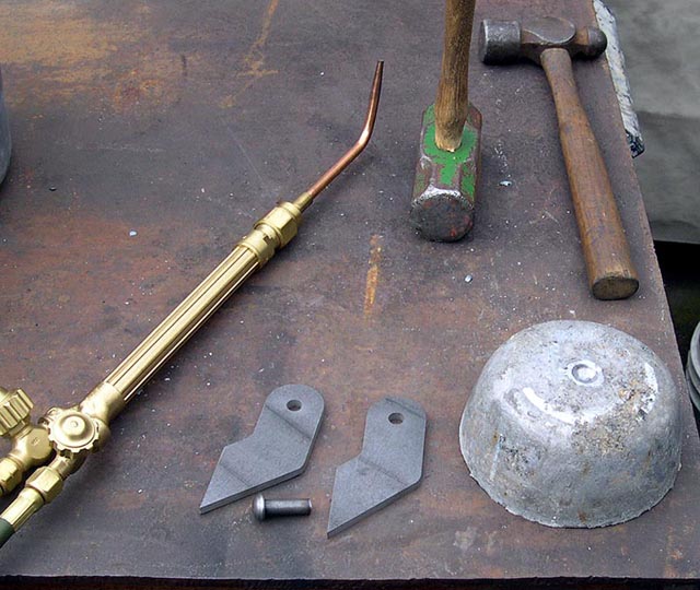
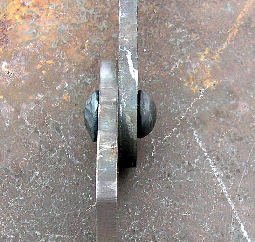
Then I assembled the hinge, put the factory head in the hole, heated the pin sticking out to nearly a welding heat (bright orange) and quickly shut off the torch, grabbed the hinge with tongs, and hammered the head to shape. I think it only took about 2 heats once I got good at it. Here are a few more pix:
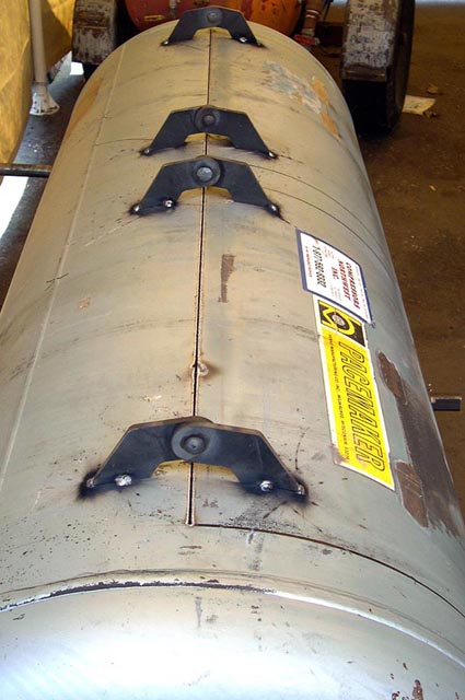
I cut the top cooker door line, then tacked on the hinges and then did the other cuts. Here's a shot of the hinges tacked on:
Here's a shot of the doors fully cut out with temporary stops on them so they don't "fall in". The doors warped when cut free, despite my best efforts.
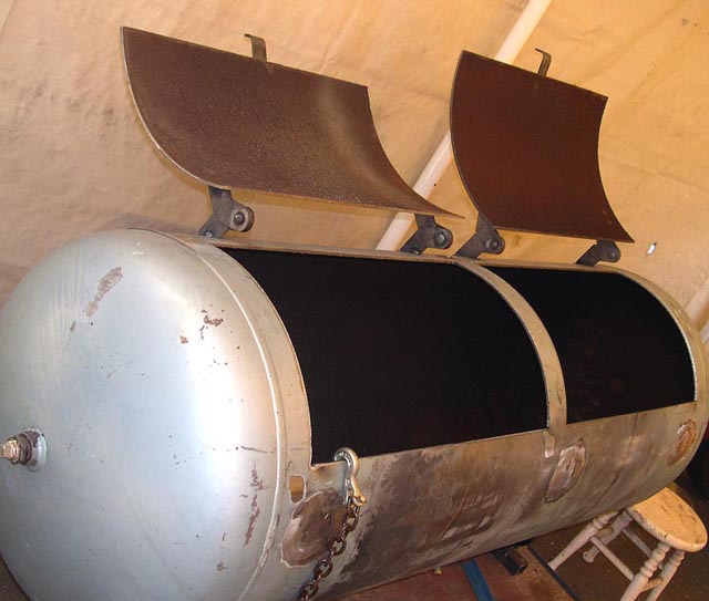
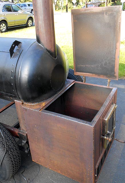
Here is the cooker with it's doors open:
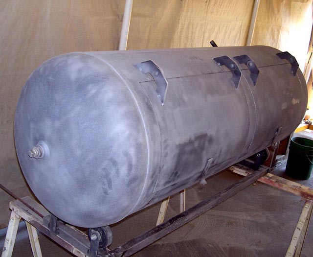
Here is a shot of the cooker after sandblasting. You can see the sawhorses and the rigid set of wheels I cobbled up. The idea was when blasting the inside of the tank to be able to roll the opening downward and just dump out the sand. But I found that wasn't really needed because most of the sand hit then swirled around and came right out. Having the tank on wheels did help later on, though.
Like everyone else, I struggled with warped doors and also the tank shell around where the doors were cut. I did the best I could when cutting, but sometimes a tank has a lot of residual stresses in it, and the doors did move some when they were cut out.
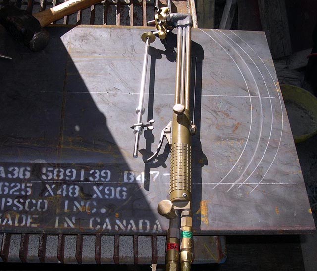
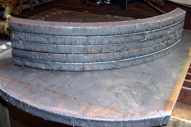
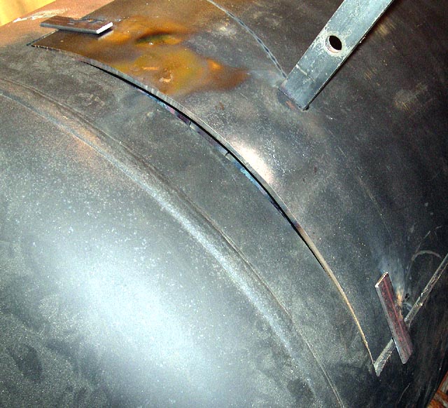
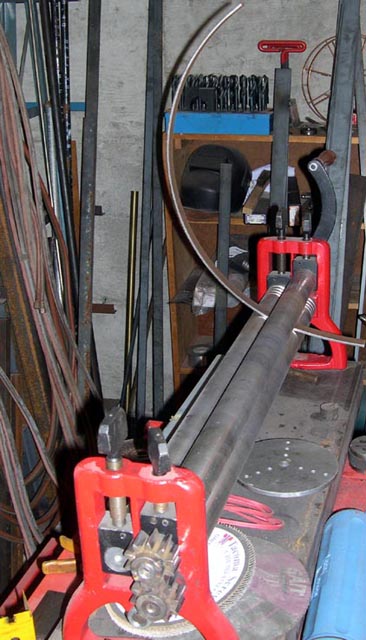
I decided to do an old shipfitter's trick and to make strongbacks that are the right curvature, and to clamp the warped material to the strongbacks and weld the strongbacks in place. I decided 5/8x1" bar would be stiff enough, but I don't have any way of forming a clean 11-13/16" radiused curve in bar that heavy. So I decided to use my good old oxy/acetylene torch and cut the curved ribs out of 5/8" plate. Two ribs for each of the 2 doors, plus 2 more just outside of the doors and 1 more for the divider makes seven parts.
Here's the basic setup. In this picture you can see my circle cutting attachment, which has two shaft collars on it so I could quickly go from one radius to the other, even with the torch lit.
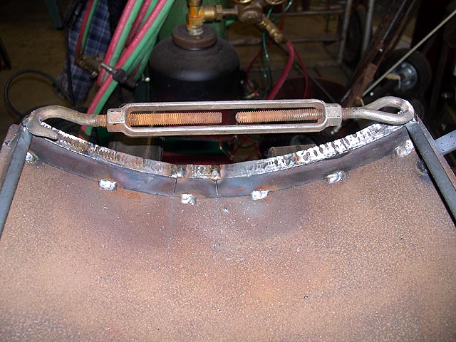
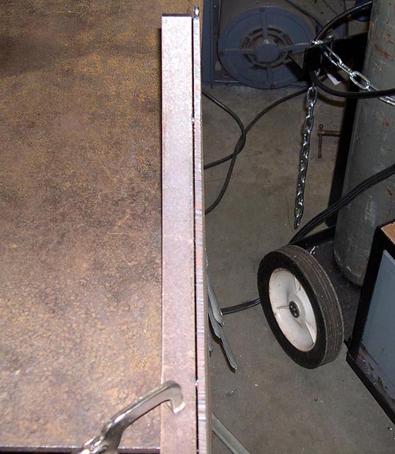
Next you see a rib in place but not clamped yet. This shows the gap which will get pulled closed. The rib being much stiffer than the 3/16" door, the door will do nearly all of the moving.
Here is that same rib installed:
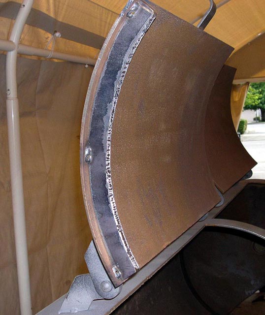
Here are a lot of flame-cut edges, which I have to say I'm pretty proud of. These were cut by hand, and it's been 30 years since I worked in the shipyards!
The curved edges of the door opened out so the curve was too flat. Worse, they did it differently on different sides of the door. The straight edges of the door were no longer straight. I used 3/8x1" bar as strongbacks on the straight sides, and 5/8x1" curved bar for strongbacks on the curved side, and the doors still didn't fit.
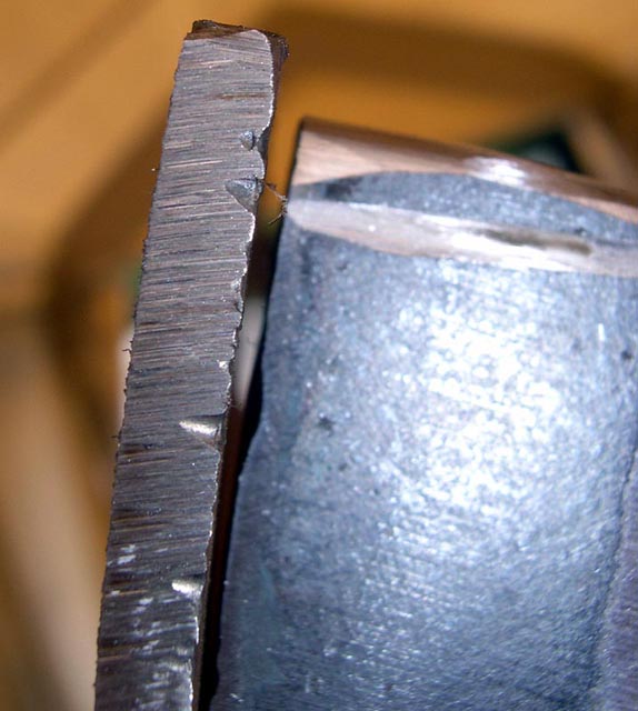
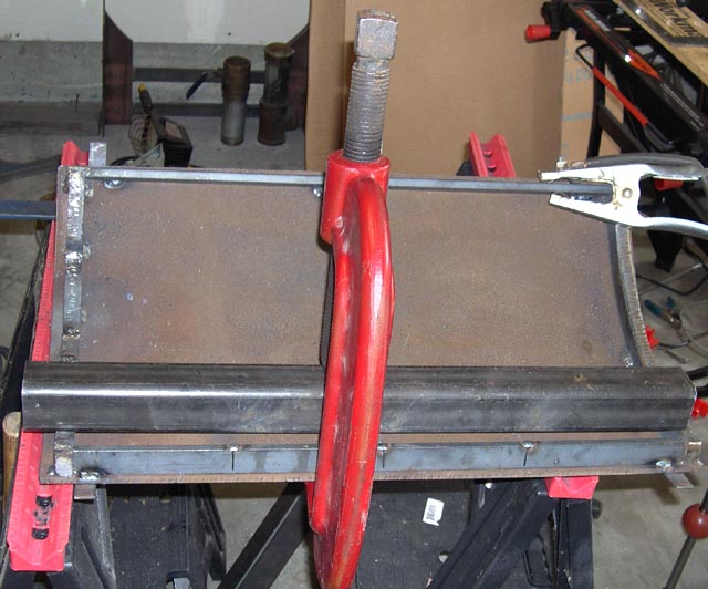
So I scratched my head for awhile and realized if I straightened the strongbacks, the door plate steel would have to move along with them. So, I got busy on correcting the one curved side that was still not curved enough. I remembered hearing about a guy who curved angle iron neatly by cutting slits in one leg every few inches all along, and then pulling the slits closed to effect a gentle curve. So I took an angle grinder with a cutoff blade on it and made a few cuts, then pulled the ends with a turnbuckle. It's a good idea to hang onto crummy old turnbuckles because they are very helpful around a welding table.
Here's a picture after I pulled the slits closed and welded the tops.
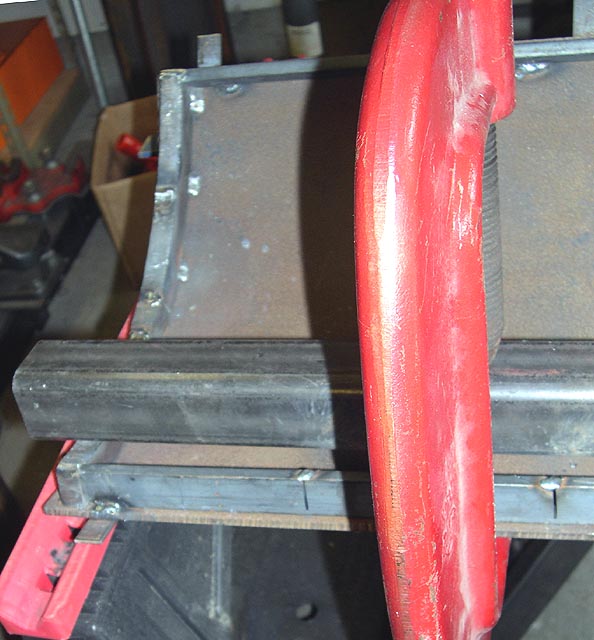
Then I went out and did a test-fit. Sadly, now the door was bowed way too much! Here's a pic, showing the edge pulled completely away from the cooker body in the middle, plus at least a sixteenth. Fortunately, it was easy to cut open the little welds and push the slits open the right amount, then weld it all back up. This pic shows the too-curved door edge before I fixed it.
Then I worked on the still-not-straight long edges of the door. This door was bowed out. I clamped it and skip-welded it to the strongback, but the strongback bent some. So I made a few slits in the strongback, then took a piece of sturdy 2x2x1/4" tube and an industrial C-clamp and pulled the slits further open. I put little steel wedges in the slits and tested the fit several times before welding. Here's my setup for pulling in the bowed-out lower edge.
Here's another view:
After a few tries, I wound up with a reasonable fit.
Here's a pic showing the resulting fit.
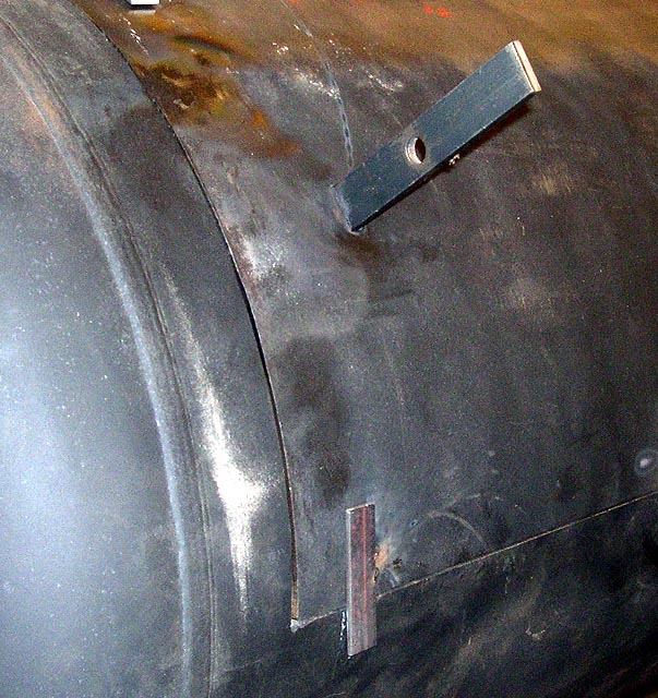
Next I added seal straps around the doors. I punched holes in the strap and plug welded the strap to the doors. Here's my setup:
And here's a pic of the doors with hinges and straps. The doors are shown with temporary handles tacked to them. These were removed later.
Next was the door handles. Here's how I decided to do the handles, in case someone wants to make them the same way.
First, I bought 1/2x5" stainless spring handles from this link. They showed up promptly and looked correct. But they were dull with no finish at all. To polish, I used a deburring wheel. It took about 2 minutes to polish out each spring.
I decided to use leftover hinge halves for my handle straps. Only thing is, they have 3/8" rivet holes and the handles take 1/2" stock. So I got my buddy to turn the 1/2" stock on the lathe, turning the ends down to 3/8" with clean shoulders. This made for an easy setup for welding. There wasn't a way to paint the shaft inside the spring handle after welding, so I masked the ends of the shafts and painted them black where the handle goes, leaving the rest clean for welding.
My little welding table has fairly straight edges which are close to square. I was able to set up the handle assembly square and true and clamped solidly in position. In the next pic you will see how I managed to get a good ground on the shaft, which is an easy slip fit in the holes and thus probably not well connected to the straps electrically. I simply hung some Vise-Grips from one end of the shaft and hung the ground clamp so it hung straight off the bottom, with gravity holding it from turning, at least somewhat.
Here's a shot of the handle setup square on, in which you can see the painted shaft inside the polished handle. Two little zaps with the MIG gun and the handle was secured to the shaft; two tiny tacks and the shaft was fixed to the straps. Then I unclamped, stood each assembly on end and plug welded the sides to the handle solidly.
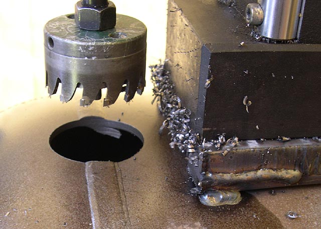
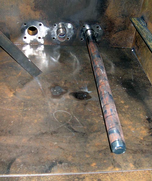
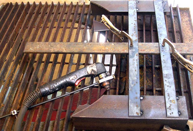
While the cooker body was still up on rollers, I cut a clean 2-1/16" hole for the washout drain pipe.
Here's the washout drain pipe before welding:

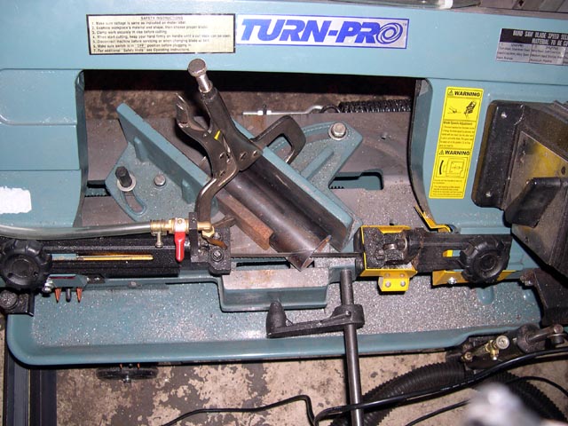
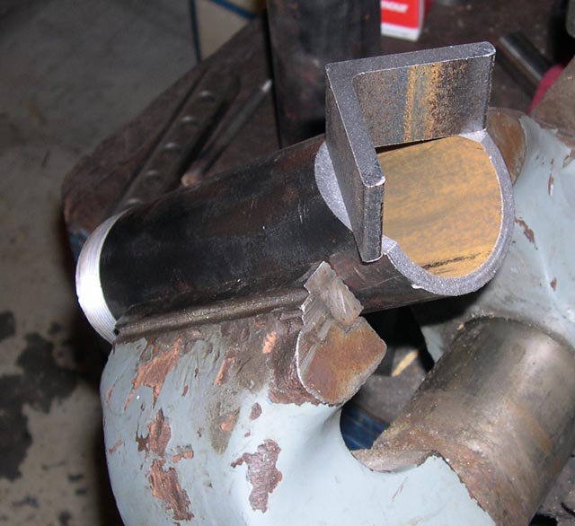
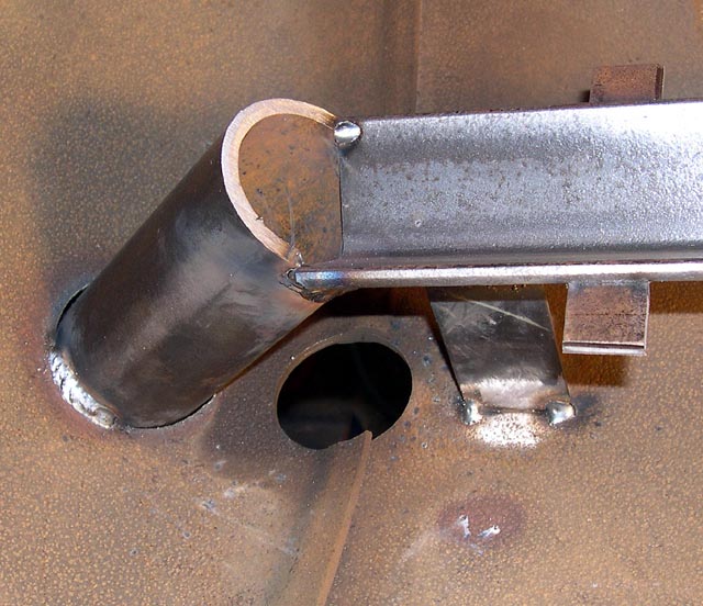
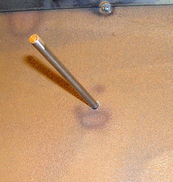
Moving next to the reverse flow plate, I decided to use a design with sides that slope to a central grease trench. The grease drains out at the lowest spot of the cooker, down a 2" drainpipe. I cut the drainpipe hole freehand with the plasma cutter. Then I mocked up the grease trench and cut/try fit a scrap piece of 2" pipe to it. I realized the two shapes would never fit together very well, but "good enough" was the order of the day. The greasepipe needed to be sliced off at the correct angle. After I did my cut/try fit on the scrap pipe (which took awhile) I was able to copy the angle using a bevel square, and to set up the horizontal bandsaw to cut the drainpipe at the same angle. The picture shows the saw cut:
With the pipe cut to the correct angle, here's how the grease pipe fit together with a piece of angle stock the same size as the grease trench:
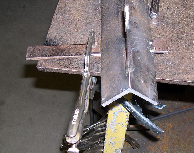
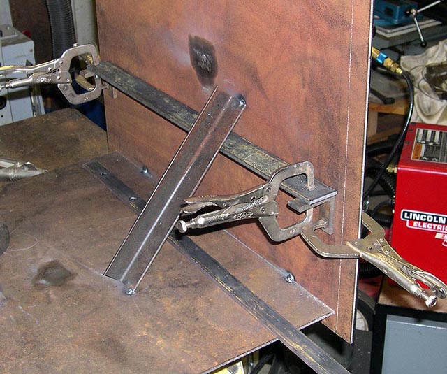
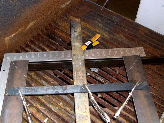
Next I moved to the grease trench. I cut a piece of angle to length, cut a little piece to blank off one end, figured the length of the supports needed at each end, then puzzled as to how to fit the support at just the correct angle. Eventually I came up with this setup, which worked great (not visible but essential is the shimming under the support piece):
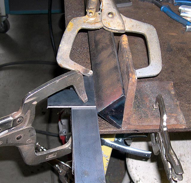
I made little tabs for the RF plate to land on. This is how I fit them so my 3/16" RF plate pieces would be flush with the top of the grease drain angle. In the next picture you can see one tab already installed (on the right) with 3/16" of space between it and the welding table. Also you can see a piece of 3/16" scrap clamped with the tab above it, with the tab hard against the angle. With this setup it was easy to get just the right spacing:
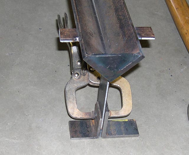
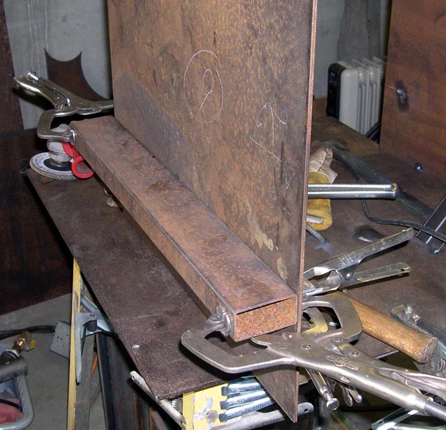
Here's the grease drain cut to length, with the hot end blanked and the supports and tabs installed. I needed a removable foot so it could stand up on its own while I was positioning it:
I fit the hot end first. There was no foot on the cold end so it could move as freely as possible, while still holding the angle at the right height. I used an 18" rule (straight all ways) to check first one side then the other to make sure the top of the angle was centered:
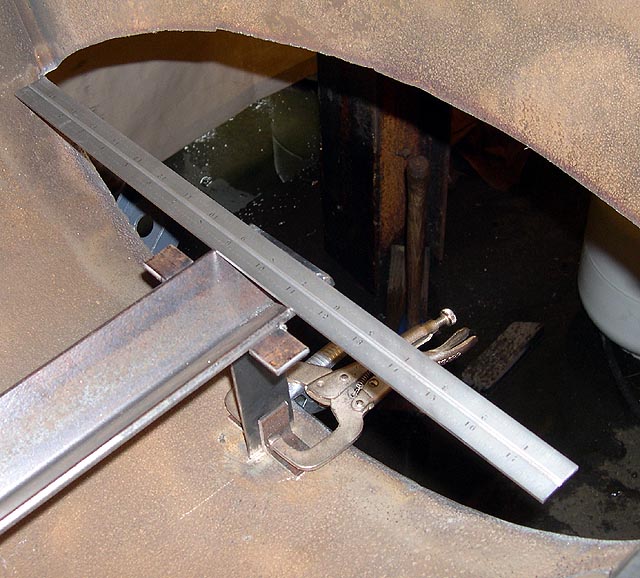
I used big calipers to check to ensure the grease trench was located in the middle. I also had to check how close it was to the firebox cut since I didn't want it to foul the firebox when I installed it later. After quite a bit of fussing I was happy. Moving to the far end, it was just a matter of making sure it was in the middle. Then I tacked the piece in and fit the drainpipe, which fit OK:
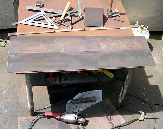
Having gotten the grease trench and drain squared away, I cut the reverse flow plates. I had calculated the dimensions, but it's easy to make a mistake so I decided to cut a cardboard template out of an old water heater box:
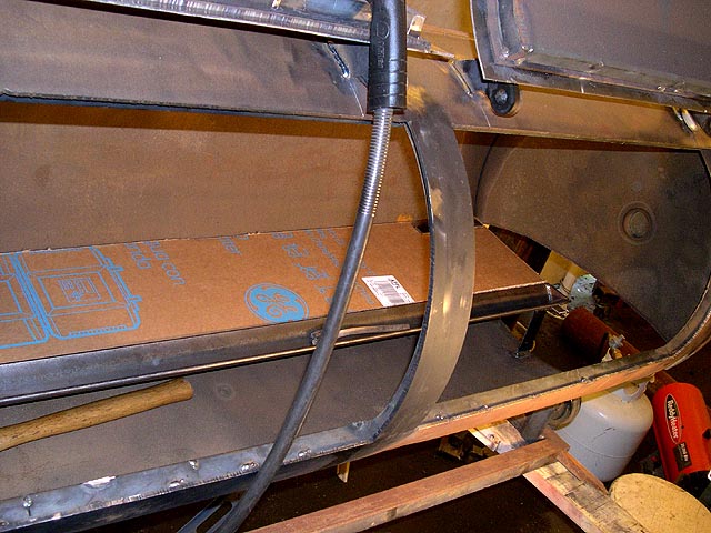
I used the template to cut out the RF plates from 3/16" plate. Note that one end is wider than the other. This is because the RF plate slopes down away from the firebox, 1-1/2" lower at the cold end than the hot end.
Before I installed the RF plates, though, it was time to get the firebox made and installed, so the RF plates wouldn't keep me from welding out the firebox/cooker joint on the inside.
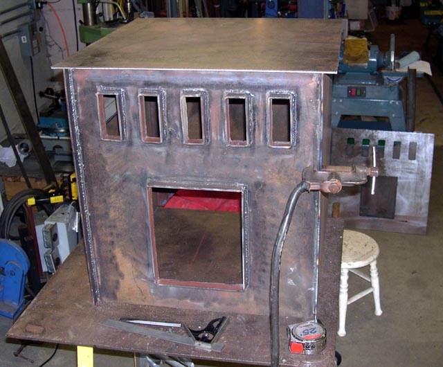
My firebox is basically a steel box, which measures 24x24x24" on the outside, and 21-1/4x21-1/4x22-1/4" on the inside. It is made from 3/16" plate, and is double-walled with 1" of ceramic wool insulation between.
The firebox is cut into the tank about 6" deep, so the top was made in two pieces. One is 7" wide and was welded solidly to the firebox and the tank. The rest of the top is hinged, and not insulated. so I can use the hot horizontal surface to heat up pots or to preheat firewood.
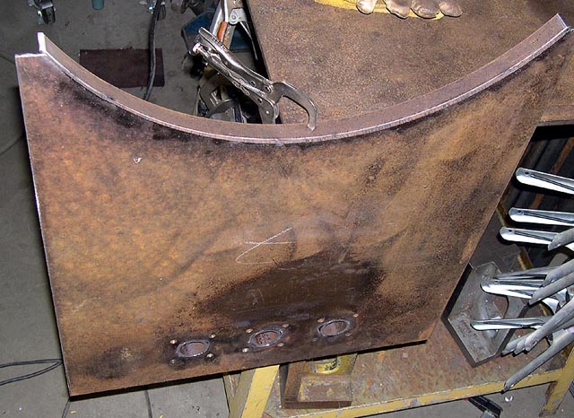
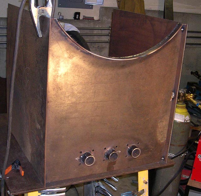
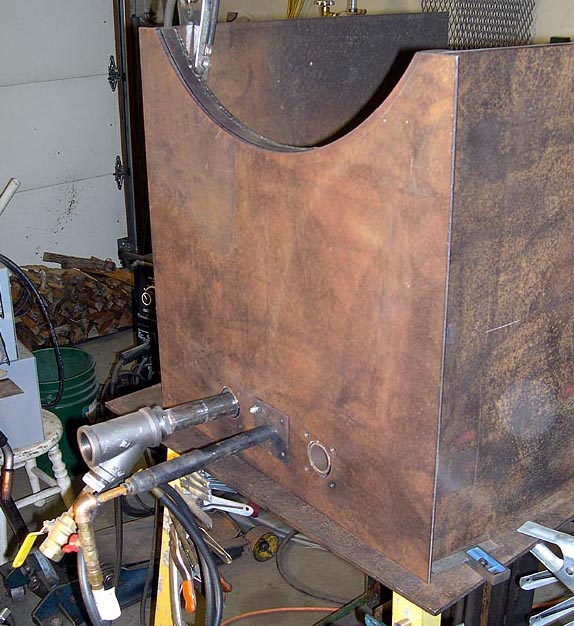
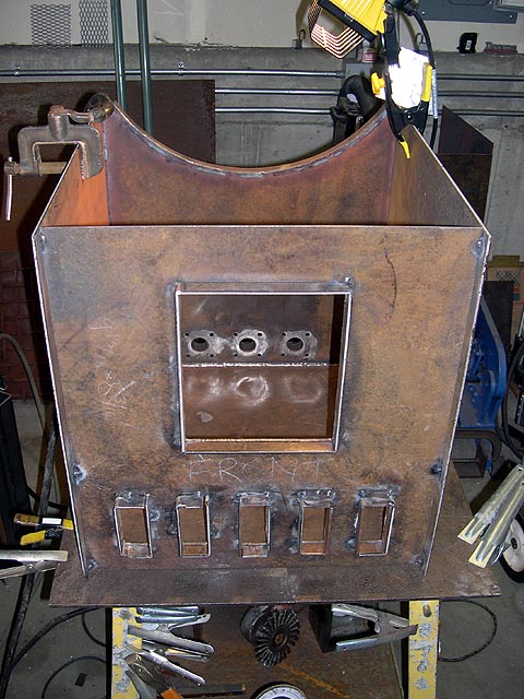
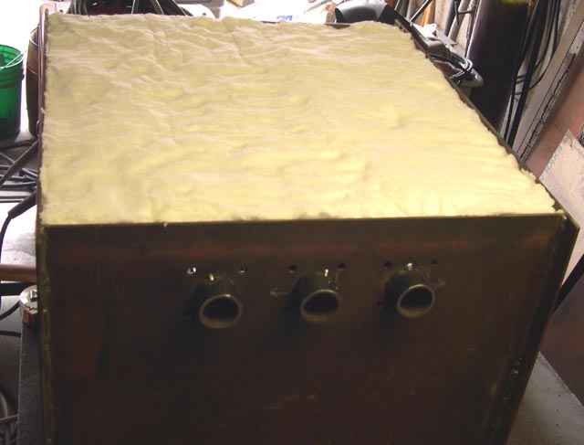
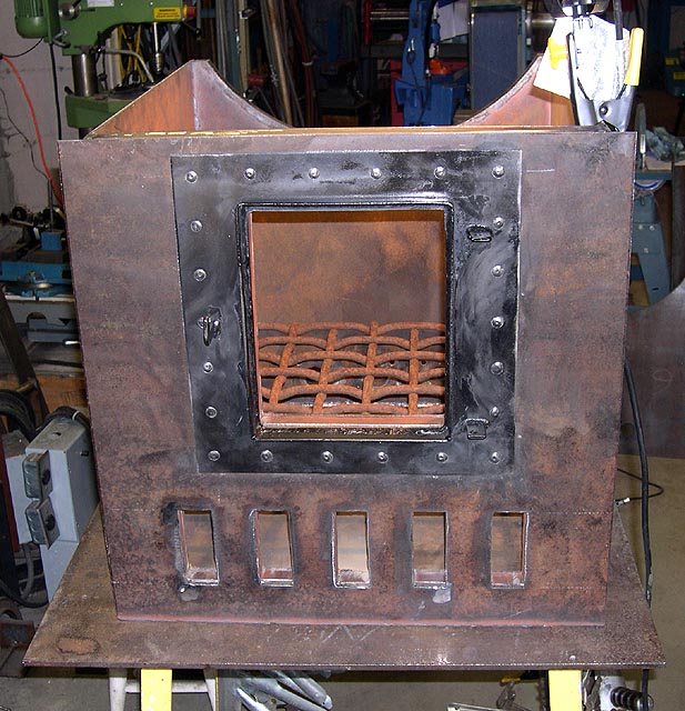
This firebox is designed to be used with wood or propane or both. At the bottom of the back are three burner ports, each with the same bolt pattern around them. I tried to be careful drilling the bolt pattern, so I could make plates easily to blank off the ports if desired. The type and number of burners can change depending on how the cooker is used. For most low-and-slow cooks, though, I use a single 3/4" pipe burner derived from Mike Porter's excellent book "Gas Burners for Forges, Furnaces & Kilns". Mike is a buddy and his burners work really well and are very fuel-efficient as well.
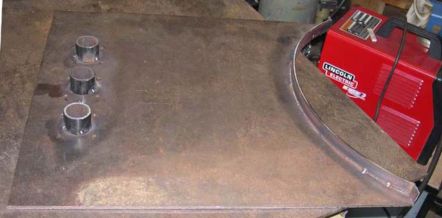
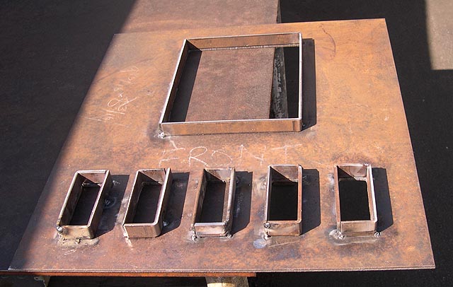
I did all the plate cutting on a 52" Cincinnati mechanical shear at a local welding school. For this design, the fit is pretty important. The pieces go together a little like a Chinese puzzle. The front and back plates have patterns cut out which had to line up exactly. I punched some holes in the waste material which would get cut out, and plug welded each pair of plates together so they could be cut and drilled as one. With the waste cut out, the plates were no longer attached, but during assembly the hole patterns stayed aligned.
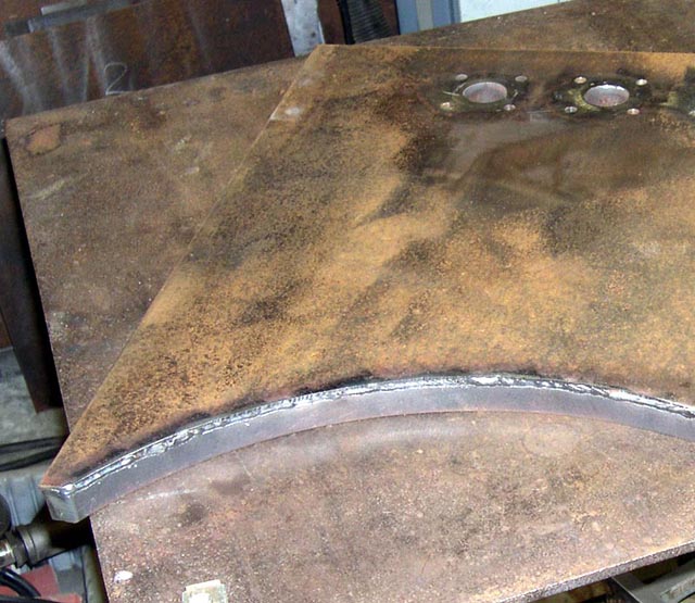
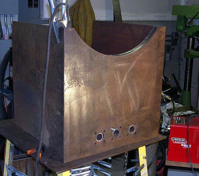
Here are two pictures of the back plates plug welded together for cutting. In the first pic you can see the 12" radius layed out where the cutout will be to fit the cooker body.
Here is a picture of the front and rear plates cut out:

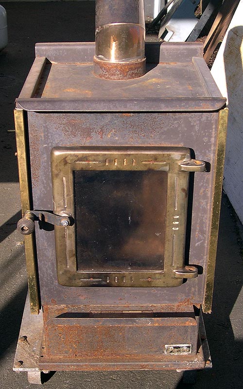
I was fortunate to find an inexpensive small wood stove. This one had spent its working life on a tugboat in Puget Sound. Its door has hi-temp ceramic glass in it. I like to be able to see the flame from the outside. This is the little wood stove:
Next I assembled the firebox. The first step in assembly was to attach the left and right inner sides to the inner bottom. The sides had to go down beyond the bottom by 1", so I set the bottom piece on a couple pieces of 1" square tube on my little welding table. Here is a pic of the first side tacked to the bottom. If you look closely you will see the 1" tube under the bottom plate. The turnbuckle set the joint square.
Next I fit the second inner side plate and tacked it. Then I added the firegrate supports, made from 1/4x1-1/2" flat stock 21" long:
I had a little issue with the other firegrate support. The plate on that side was warped so I pulled it straight with a strongback:
Next I finished up the inner back plate assembly:
I used 3/16x7/8" strip to cap the 1" gap between the inner and outer walls. Fit properly, this left a 1/16" gap on each side of the strip for better weld penetration:
Here is the inner back plate ready for install:
Then I tacked it in:
Here is the outer back plate set in position and not tacked. Before welding, a layer of 1" ceramic wool insulation goes between it and the inner back plate:
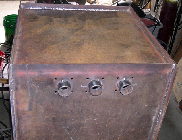
I put two pipe burners into two of the burner ports to give an idea of how they work. This is a temporary setup with the outer back plate just set in position, for purposes of illustration only. The burner made from half inch pipe is a small forge burner I used to use on a different cooker. It has a mount plate with the same bolt pattern as I used on this cooker, and is held in by one bolt. The one made from 1" pipe is a prototype grill burner inspired by this thread:
Shown from the outside:
and from the inside:
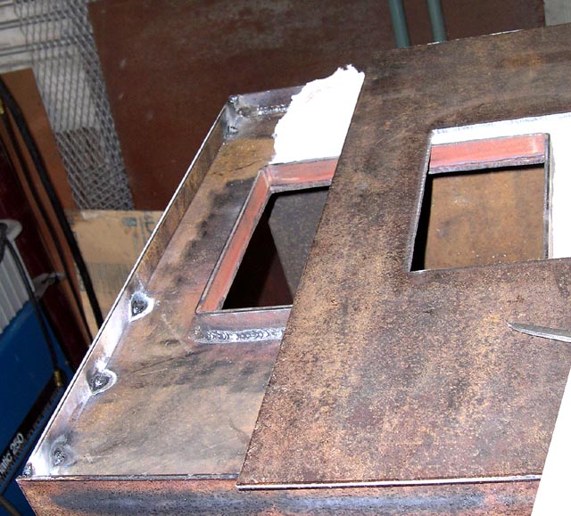
Here are the spacers around the air inlets and the viewing door on the front inner plate:
And here is the inner half of the firebox with the front piece tacked in. You can now see how the outer plate will be spaced out from the inner, with 1" ceramic wool insulation between.
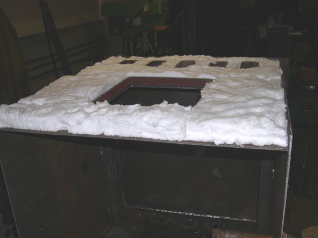
After I welded up the front inner side, I flipped the firebox over on its top. Here is a picture of the bottom where you can see how the space for the ceramic wool:
The ceramic wool is 1" thick, 8 pounds per square foot, and the roll is 24x300". Here is a picture of the box:
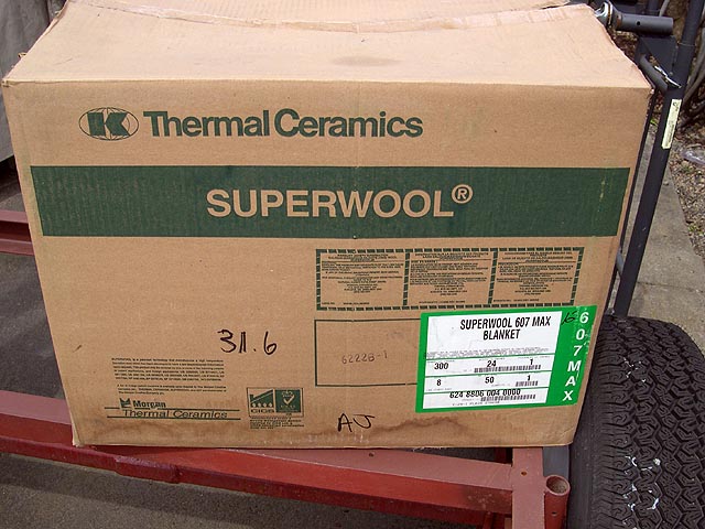
Scissors worked best to cut it out. It's like cotton in that if you cut it a little wide you can just stuff it in. Also, you can fill in low spots with scraps. It isn't itchy stuff like fiberglass, either. I cut out a piece to fit the bottom of my firebox and set it in. I used no cement.
To install the ceramic wool I'd turn the box side to insulate uppermost, lay in the insulation, put the outer plate over it and weld it. It had no problem with red heat from the back side of weld beads. Here's a pic of the bottom insulated before the outer plate went on:
Here's a picture with the outer bottom plate tacked on. The plate was tacked from below, but I flipped the box over to weld it in the horizontal position. You can see how the bottom plate sticks out an inch, forming the first side of the cavity which will insulate the side.
I turned the box onto its back and insulated the front. I was able to take advantage of the flexibility of the insulation. It was easy to cram it into the crevices. In this shot, there will be a 1" wide strip welded across the top of the front (the side nearest the camera) and the front plate will stick out the sides an inch, forming the second sides of the insulation cavities. See the pic:
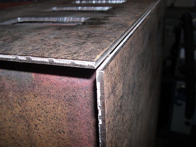
This picture shows how the outer corner joints are fit up. Neither plate overlaps the other - I designed it to leave the joint fully open. This will allow a strong weld. Here's the joint:
When I sheared the 3/16" plate for the firebox, I knew I'd need a bunch of 3/16x7/8" strips so I sheared several. They came off the shear warped and twisted. To use them I had to cut a piece to length, then put it in a vise and twist the other end with a big wrench until I got as much of the twist as I can out. Then I took it over to the anvil and hammered it flat, then put it up on edge and hammered any curvature out. This is how I made the piece that goes across the top of the front side's insulation. Then I fit it and tacked it into place. In the next pic you can see how it completes the cavity which holds the 1" ceramic wool insulation:
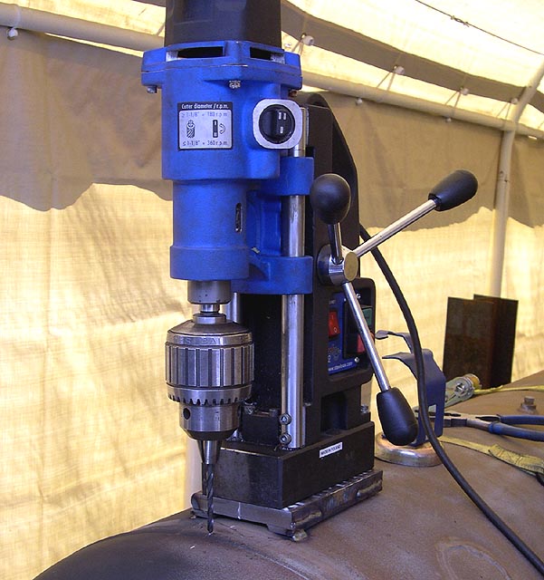
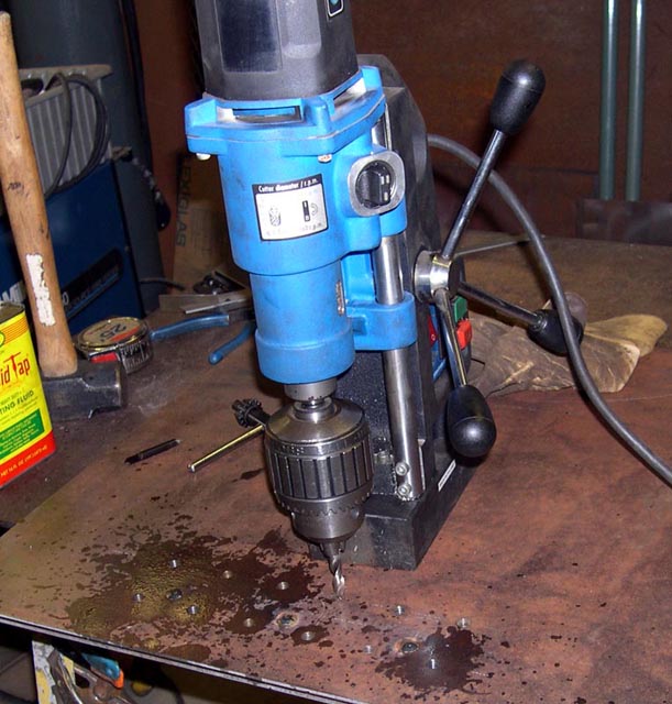
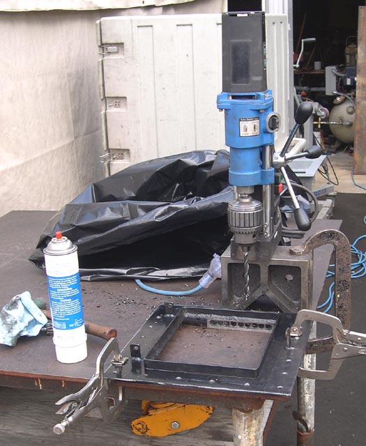
To use the nickel-plated cast woodstove door, I scrapped the stove out, saving only the door and the front side of the woodstove. I cut that front side as square and straight as I could, and drilled a uniform hole pattern around the edges. I was taught the best way to weld two lapped plates is to punch holes in one and then plug weld it to the other. I drilled the holes on my outdoor welding table using a mag drill. To keep from drilling straight into the welding table top, I set the piece up on some old milling parallels and a homemade 123 block, and clamped it in position for each hole:
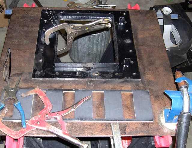
I could have burned the holes with a torch which would have been quicker but it wasn't raining outside and I wasn't in a hurry. I decided to leave the plug welds as welded, rather than sand them down flush. The idea is they look like rivets. I did the plug welding with a MIG welder, inside with the door closed so the wind couldn't blow the shielding gas away. The piece with the holes in it wasn't all that flat, but I clamped it tightly between each weld. Here's my setup:
With the door frame welded solidly to the front plate, I finally got to fit the front plate carefully so all the holes lined up as best I could get them. I tacked it in solidly and welded the outer corner joint 100%. Then I trimmed an old pig screen for a firegrate, and put it in. You can see it in the next pic, which shows the box upright. Two sides insulated, three more to go!
I like the look of the plug welds, but if I change my mind later I can always sand them smooth.
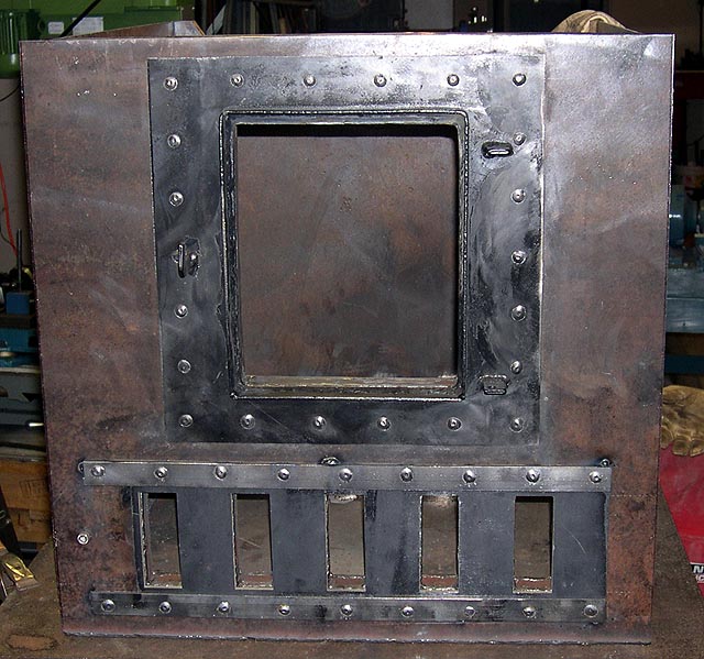
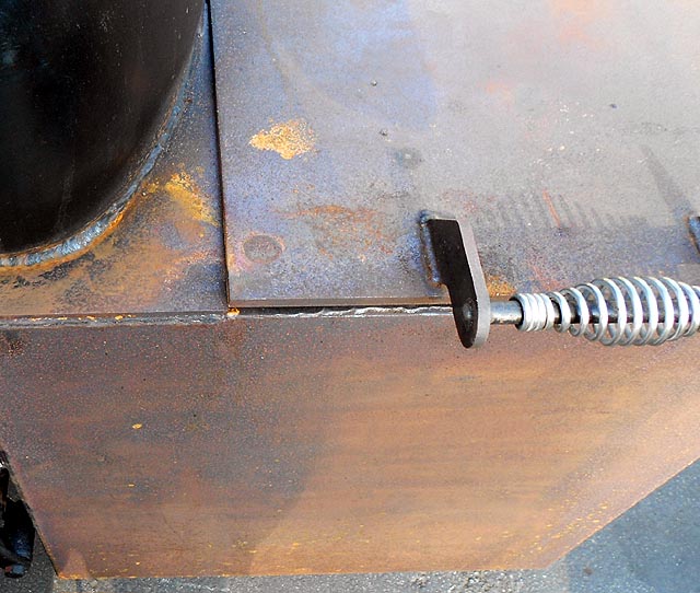
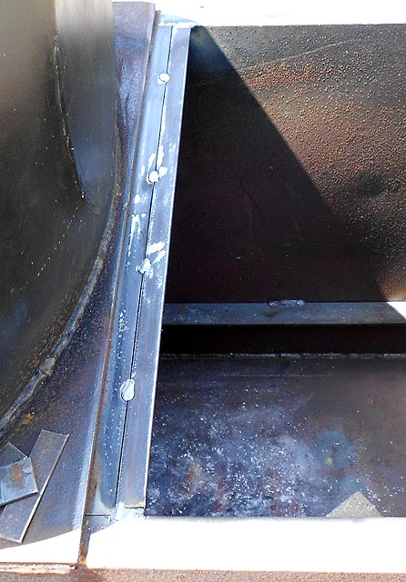
I tacked in the slide damper guide bars. If you look carefully at the left side of the damper you will see a stainless socket head cap screw which acts as a removable stop. I want to be able to remove the slide damper in case stuff gets in the tracks and it starts to bind. For now, it slides easily. I left some clearance above, below, and between the damper plate and the guide bars that overhang. The damper stop on the right side will just be a welded bar, but in the next picture it isn't fit yet.
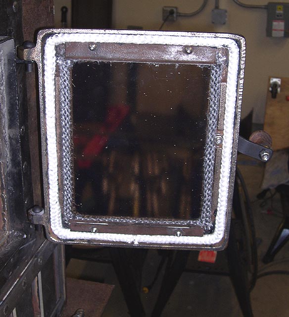
I hadn't rebuilt a wood stove door, so I was relieved when the job turned out to be straightforward. I disassembled the door and cleaned the ceramic window. Some people think that's glass but it isn't. If you ever scrap a wood stove, save the window from the door. They are very expensive if you have to buy them. I also derusted the latch bar, refinished the wood handle, polished its brass ferrule, and replaced all the fasteners with stainless.
Here's a pic of the door with new gaskets:
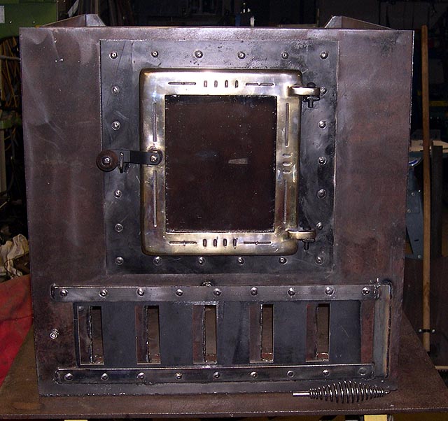
And here's a shot with the door installed. You can see the slide damper's handle lying in front - it's just an old slag hammer with the head cut off.
Here is a picture of the firebox before painting and installing:
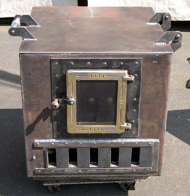
I installed the firebox as is, with a plain flat 3/8" lid, and used it that way for some time. But the lid warped. Later on I'll show you how I reworked it. In the meantime, here is the firebox install. I lifted the firebox into position with an engine hoist. There is a light inside the cooker body.
I took advantage of the smoker still being up on rollers to turn it one way and then the other to make welding it underneath a whole lot easier:

Here is the firebox installed and welded:
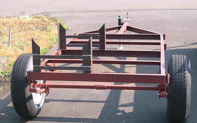
After welding the firebox, I installed and welded the RF plates. This cooker was to be installed on a little flatbed trailer. I derusted and primed the entire trailer, straightened and reinforced the frame, and moved the axle back. I also removed the fenders, lights, wiring, and license plate.
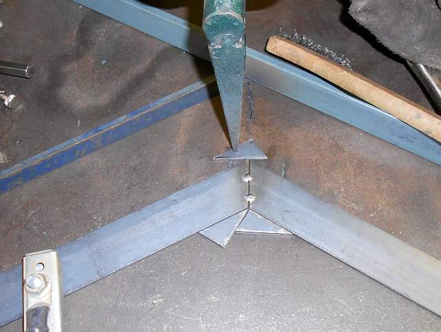
I made up some simple legs for the cooker. Each leg is made from two pieces of angle iron held in position and braced by a crossmember. The angle iron is cut at a 12" radius to accommodate the 24" cooker body. Here are some pictures of how I fabricated these legs.


Here's the trailer with the cooker legs just sitting on it.
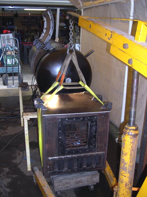
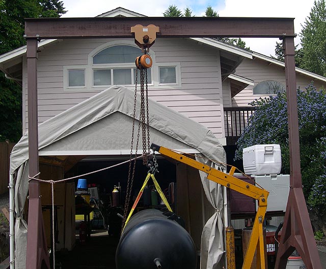
To install the cooker on the trailer, I tried to get the cooker level side-to- side before I picked it up. I also picked it at the balance point, if for no other reason than I wanted to know where the center of gravity was with respect to the trailer axle, which I'd moved to the rear as far as I could. Here's a shot of the engine hoist picking the cooker off the sawhorses:
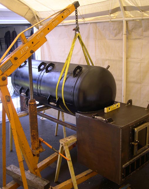
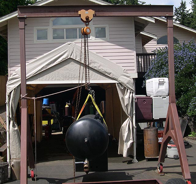
Once I got it up in the air and stable, I removed the sawhorses and rollers and then used the wheels on the engine hoist to roll it under my gantry. I figure this was between 700 and 800 pounds, about the limit of what you can get away with moving on engine hoist wheels which aren't designed to roll under a large load. Anyway, the next shot shows the load being transferred from the engine hoist to the gantry's overhead hook. I wasn't able to unrig the engine hoist's hook so I simply unbolted its lifting chain and let it be until later. Here's the handoff:
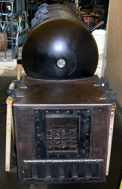
After the handoff I removed the engine hoist. Here's a shot of the cooker hanging from the gantry. Note how well it is balanced, which made it a lot easier to deal with:
I got the cooker down onto solidly tacked legs:
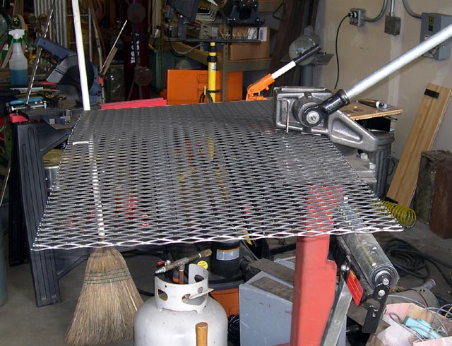
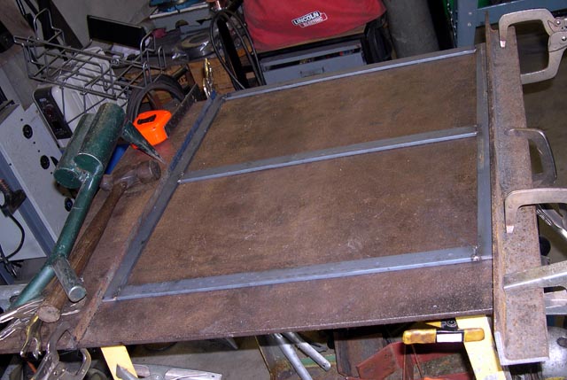
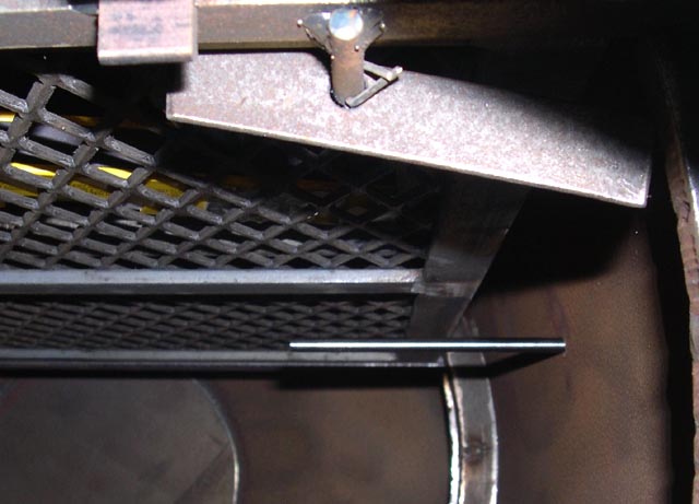
I fitted the cooking grate supports, complete with tipout and pullout restraints, and then I fabricated the cooking grates themselves. I know the conventional wisdom is to make rectangular frames from 3/4x3/4x1/8" angle and then cover the top with 3/4-9 expanded metal, but that makes the grates 7/8" thick and in a 24" cooker that's just giving away too much headroom. I make a simple frame from 1/4x1" flat bar - no coping, no requirement for super-square ends, just shear them up and weld them.
I started by cutting up the 3/4-9 expanded metal sheet. First I cut it into rough pieces using the plasma cutter. Then I cut the pieces and trimmed them to size using a Whitney no. 38 hand shear. This tool does a really great job on expando. Here's the tool:
Here's a piece partly through shearing:
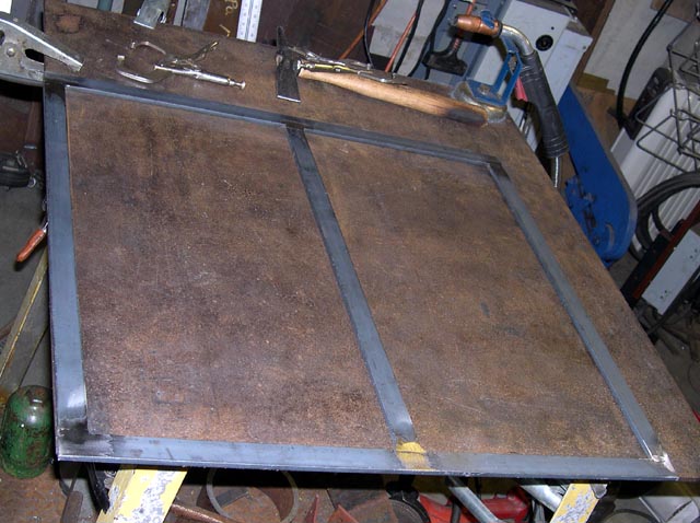
After I got all 4 pieces cut out, I sheared the flat bar up. I clamped a couple of pieces of angle to my little welding table to use as a jig:
Then I sanded the welds flat:
And used the MIG welder to weld on the expanded steel:
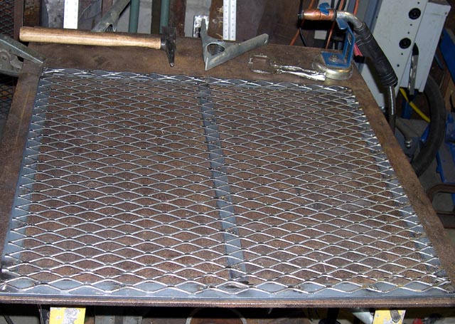
Here's the cooker with the grates pulled partway out:
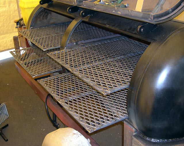
The cooking grates are 3/8" tall, half an inch shorter than the normal kind. This way there is 6" above each rack, which is large enough for whole chuck roasts, the largest pork shoulders, and large birds. Maybe not turkeys ..
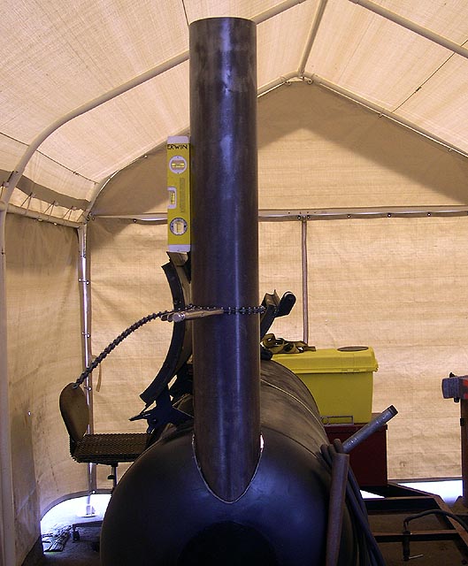
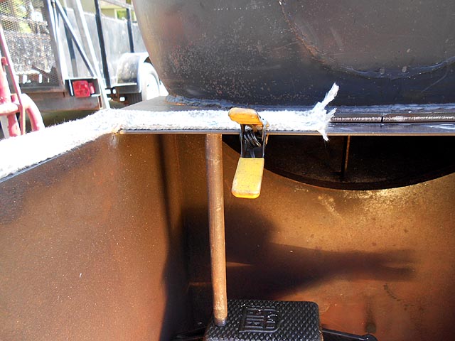
Moving on to the stack. Of all the kinds of fitting there are I think the thing I'm worst at is fitting pipes, which includes tubes. Any time I have to do complex joints, fishmouths, or the like, I'm not very good at it. I had obtained a piece of 6" 13 gauge tube (.089" wall thickness, pretty stout) about 42" long and had earmarked it for the stack on this project. Both ends had been buggered up and I was able to get my horizontal bandsaw adjusted to give me reasonably square cuts.
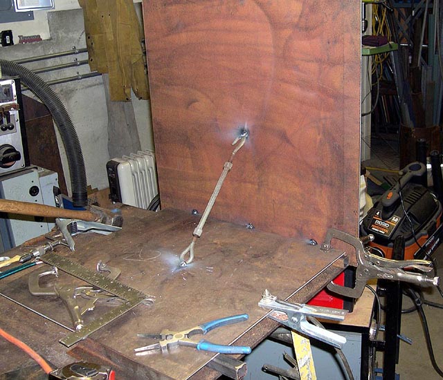
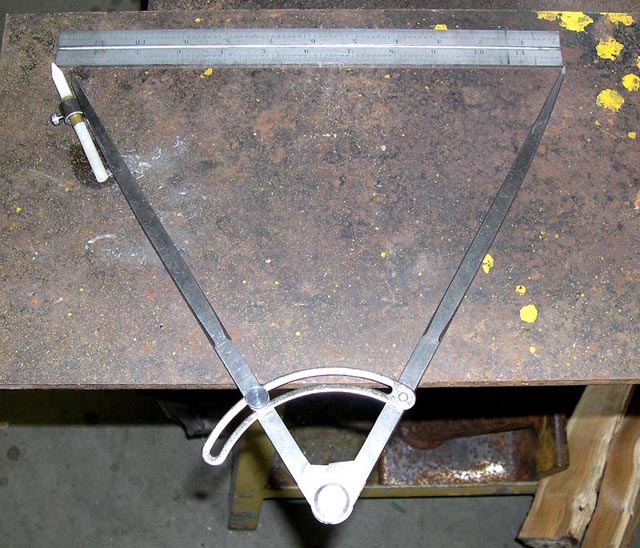
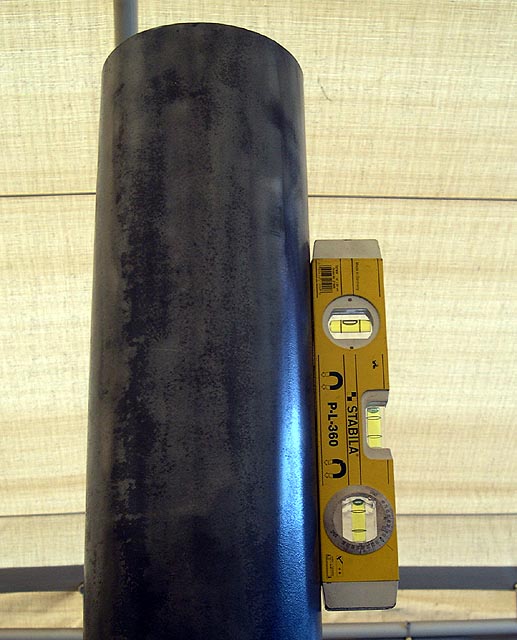
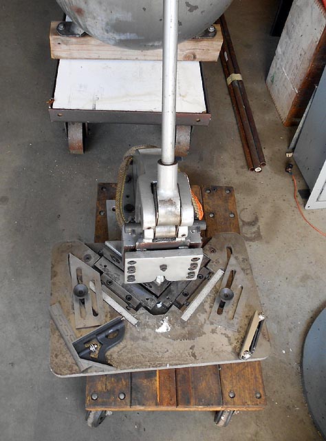
This was a pretty extreme case of scribing and cutting one piece into another. Big long awkward piece up top, trying to hold it in exactly the right place, exactly vertical both side to side and fore/aft, and then holding up a 6" rule and drawing a line on top? Working alone as I did through nearly this whole project? Wasn't going to happen. So I made a jig to hold the pipe. I held the jig to the smoker with a ratcheting strap, and held the stack pipe to the jig with a Vise Grip chain clamp. This let me dial in the level both ways, and have both hands free to do the soapstone/6" rule thing and get an initial place to cut.
These pictures show this setup.
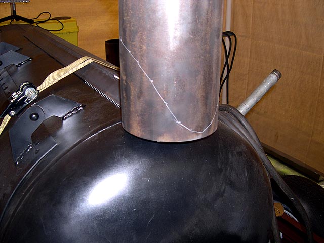
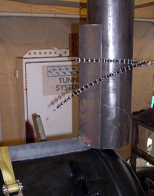
Once I got the line (I just guesstimated the line inside the jig where I couldn't scribe) I used the plasma cutter to make the cut on the sheet metal tube, and a variety of handheld and fixed abrasive machines to smooth the cut. I got the stack trimmed, the hole cut in the smoker tank without too much gap, and got the stack clamped to the jig. With the trailer level and the stack vertical it was ready for tacking. In the next images there is a bright light inside the smoker body shining through the gap.
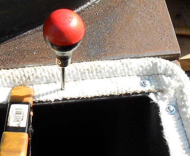
Next I made thermometer ports. My thermometers have 6" stems. I wanted them where they barely use any cooking space, and so their stems didn't foul the shelves on the inside as the doors, and where the thermometer dials are nowhere near hitting on the outside when the doors are opened fully. So I chose to put them centered on the doors, slightly below the bottom of the upper grates.
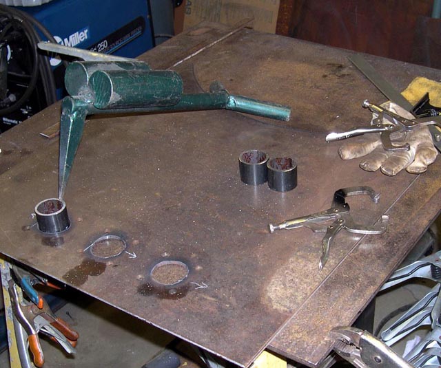
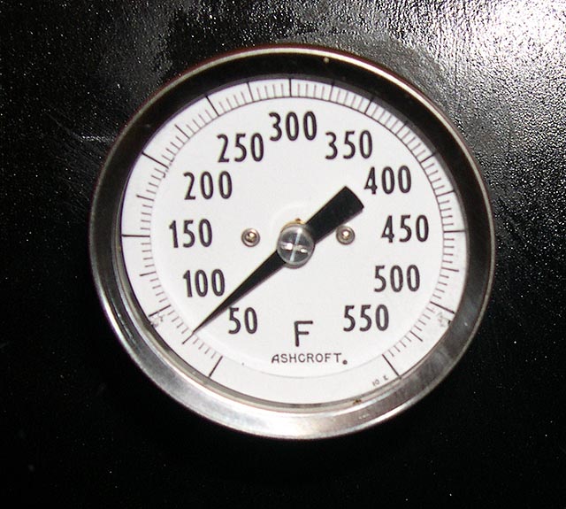
A note on the thermometers themselves: around 2010 Grainger was closing out the Ashcroft industrial thermometers with 2" dials, 1/4" NPT back mount, and various stem lengths. These are calibratable thermos of good quality, and they were about $10 apiece IIRC so I got them. I would have liked to spring for a pair of Tel-Trus but I just comforted myself with the thought that if I thought a little about how I mounted them, someday I could buy the Tel-Trus and just screw them in. Those have 1/2" NPT back mount threads and 1/4" stems, while mine have 1/4" threads and 1/4" stems. I decided cut a 12" radius into a pair of 1/2" pipe couplings, weld them on, drill 1/4" holes in the center for the stems, and use pipe bushings to mount my thermometers. That way if I ever want to upgrade to Tel-Trus I can just unscrew the pipe bushings and thread the Tel-Trus right in.
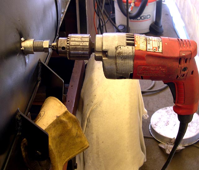
It isn't easy to drill a 1/4" hole located in the center of the pipe bushing, with the door at an angle - the drill bit would wander. So I had my buddy turn me a special drill jig. It is threaded 1/2" NPS (those couplings are straight thread, not tapered) on the outside, and bored down its center for 1/4" drill bit to clear. After installing a radiused pipe coupling, I screwed in the drill jig, and used an electric drill to make 1/4" holes. The jig allowed me to locate the holes exactly in the centers of the pipe fitting, and the thermometers with their pipe bushings threaded right in with no binding.
This shows the drill jig with my old Milwaukee 1/2" hole shooter:
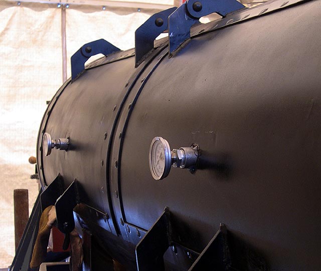
Here are the thermometers mounted:
Here's a closeup of one of the thermometers:
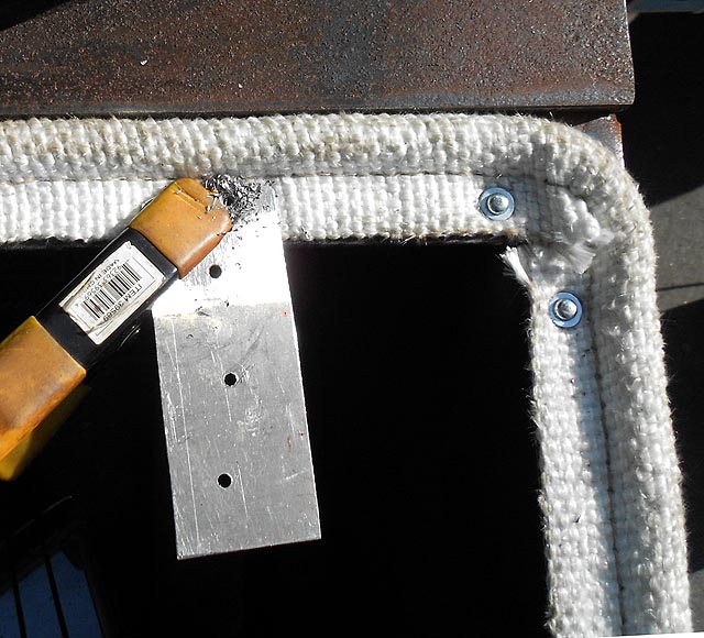
The holes I drilled for the thermometers fit closely to keep much heat and smoke from leaking out:
In the next pic you can see where the thermometer stem is located relative to the upper cooking grate. You can also see my pullout restraining devices. They are very simple. There is a 1/4" pin welded to the bottom of the cooking grate support, which sticks out below the cooking grate itself. There's a short bar with a 5/16" hole (sloppy) which is longer on one end than the other so it wants to tilt back. The short end is mitered so it will catch the bottom of the cooking grate unless the long end is lifted. This keeps small kids from pulling the grates out, and it's really easy to reach.
The next picture shows both the welded-up stack (some of it, anyway) and how even with the door fully open, the thermometer cannot hit anything:
![]()
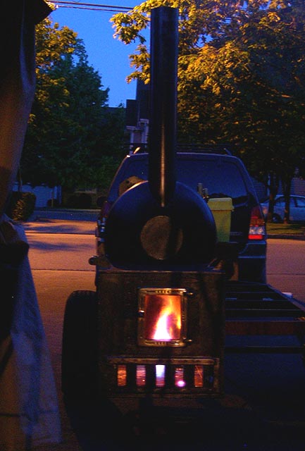
Here is the first fire in the new smoker. :
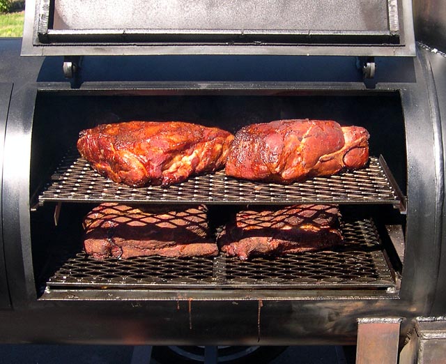
And the first cook, some pork butts and chuck roasts. The cooker doors sealed just fine, not a hint of leaking:
After some use, I decided to fix the firebox lid. It had warped enough to let smoke escape on three corners:
The door which had dropped cleanly closed when I first made it, binds fairly severely and requires force to close it.
I cut the old door loose. I ground away the vertical hinge welds until they were very thin, then a few taps with a hammer and the lid came off.
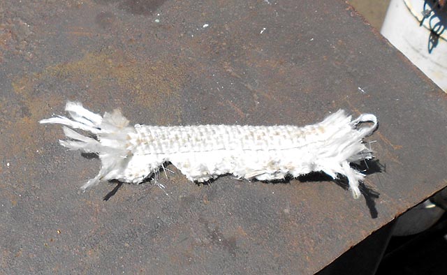
I bought some fiberglass tadpole gasket material to solve my lid leaking problem. The good news is that it should seal and seal well. The bad news is that I had no idea how to work with it. Also, the lid won't look as clean closed because it will sit up on top of the gasket nearly 1/2". I decided function was more important than form and ordered the tadpole gasket from McMaster, figuring I'd find a way to get it installed despite having no idea at all how to work with the stuff.
I found very little on the Web about how to install tadpole gasket, so I decided to carefully document what I did to pass it along in the hopes that it may help someone else.
The first thing I found out about tadpole gasket was that it frays horribly when you cut it with shears or scissors. I tried taping over the gasket and cutting through the tape. That got me a much cleaner cut, but when I went to remove the tape it frayed worse than ever. In the end I wound up making my cuts with a sheet metal shear.
The second thing I found out is that the fiberglass is the horribly itchy kind. Bummer, but nothing I could do, so I soldiered on.
The biggest thing I didn't know how to do was to go around a corner. Some guys say to cut four individual pieces and just butt-join them at the corners. With the rather extreme tendency to ravel, I wasn't wild about that idea to say the least. So I figured I'd run one gasket all around and just have one butt joint partway along one edge, figuring that would be the best I could do. The next thing I had to figure out was how to remove material from the flat part so it could bend around a corner without bunching up and forming a big thick knot with no give to it. I figured I could either cut out a square notch or a 45 degree notch. Again, I figured the method with fewest cuts would fray the least, so I chose the 45 degree notch. I tried cutting one out with shears. I'll show you a picture of how that worked out in a second. Then I realized a new toy I just acquired, still sitting on a mover's dolly in the front door of my shop, might work a whole lot better. It's called a sheet metal notcher, and it did a nice job. Here's a pic:
And here's a picture of a small scrap piece. On the left is a fairly clean notch made by the notcher. On the right is the same sized notch I cut out with shears, except it frayed so badly you can't even see where the notch is!
I measured and made all my cuts at once. After the cuts were finished I handled the gasket as gently as I could because of its tendency to fray and unravel.
With my gasket cut, I had to do a a little metalworking before I was ready to start installing the tadpole gasket. At the back of my firebox lid was a 1/8x1" piece of steel strap which sticks out 5/8" for the lid to seal against. This wasn't wide enough, so I skip welded in a piece of 1/8x3/4" strap the width of the firebox. That made the sealing surface 1-3/8" wide all the way around. My gasket material was just over 1-1/4" wide, so this worked out well.
With a nice surface to attach the gasket to, I then turned to how to actually attach the gasket. I considered self-tapping screws, but rejected them because I didn't want sharp screws sticking down from the 1/8" strap at the back of the firebox. Then I considered pop rivets. I found one size that would work well with the gasket material and the 1/8" strap. But I worried that the flat weave might work loose around the small rivet head, so then I abandoned that idea. Eventually I decided to use what machinists call drive screws, which my hardware store calls u-drive screws, with a small washer to increase the bearing area. I wound up using no. 6 x 5/16" u-drive screws along with no. 6 steel washers. Here is a picture of a screw, upside down, with a washer slipped over it, held in place by a small magnet:
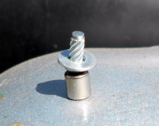
The heads of these screws are round, like rivet heads. You just hammer them in. I found that a 1/8" drill bit worked OK for no. 6 u-drives, even though they called for 1 number 31 drill, just a few thou smaller. But 1/8" bits are tight enough, and I buy those by the package lot so I knew I would have plenty. To avoid having to align a rapidly fraying hole with a nearly-invisible 1/8" hole in the steel, I decided to drill right through the gasket material and the steel in one go. I tried this first on a scrap piece, and realized that this gasket material has a tendency to wind up on the drill bit and cause a rats nest. So I drilled a 1/8" hole in the end of a piece of sheet metal scrap and clamped the gasket down with that and used the sheet metal as a drill guide which had the side benefit of keeping all the fibers in place.
Here's a picture of my sheet metal clamp/drill guide clamped over a piece of scrap gasket. In this picture you can also see the head of a u-drive screw.
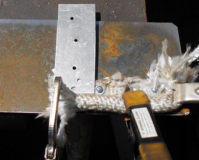
My procedure was to clamp the gasket to the sealing surface with my sheet metal/drill guide. Then I'd drill with a 1/8" drill bit, then remove the sheet metal and use a small scratch awl (pointed tool) to align the holes. Using the tapered awl also had the effect of leaving a clean hole to insert the u-drive with washer in.
The steel strap at the back top of the firebox was easy to drill through, but would not have stood up well to beating the screw in with a hammer. So I used a scissor jack and a piece of 3/8" pipe to back up the strap and give me something solid to hammer against.
After I drilled each hole, I used a shop vac to pick up the small bits of swarf and cut fiberglass fibers. The next picture shows the sheet metal drill jig, still clamped, as well as the swarf left by the drill. You can also see how the corners worked out, as well as how the drive screws with washers look compared to the tadpole gasket.
I wound up putting a screw roughly every 3 or 4 inches. In the end, there was a little fraying at the corners, as well as at the butt joint in back, but overall I was really pleased at the install. With the gasket installed, I set the lid on top overnight to see how much the gasket would compress. Then I fit and welded a cross-brace to the lid (pulling it flat again) and reinstalled the lid.
The next detail I worked on was an adjustable stack damper. I may drive while my smoker has a fire in the firebox. I wanted my stack damper to stay put. The damper plate, support plate and angle location plate were cut by my buddy's waterjet.

This damper "kit" installed very quickly and works great.


With the weight of the smoker all the way on one side of the trailer, the trailer sagged badly, tilting to the left. I decided to beef up the leaf spring under the heavy side of the trailer. I bought a cheap helper spring kit at the auto parts store and, with a few minor modifications, installed both halves right in the middle. It didn't solve the problem but it took out at least half of the lean. At least now I don't have to feel ashamed when I'm towing it. When I get to the cook I use a small jack to level it side to side anyway, helps keep the temps even.

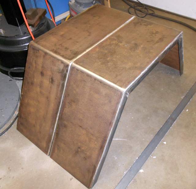
After reinforcing the suspension under the smoker, it was time to add fenders. I have a lot more time than money these days, so I opted to make my own. I decided to use a jeep-style design, like half of a hexagon. To be legal in Washington State, a fender must extend down to the center of the wheel. I decided to make my fenders have 3 equal sections each 18-1/2" long, bent 120 degrees to form the half-hexagon shape. The 18-1/2" sides fit nicely over my 14" trailer wheels with tires.
I had a piece of 1/8" plate so I had two pieces sheared 10x55-1/2". Then I used a shop-built press brake to make the 120 degree bends. I cut 18-1/2" long pieces of 1/8x1-1/2" strap and sheared both ends at a 30 degree angle. I made 12 of these for the 4 fender sides, 3 pieces per side. I saved the little sheared-off 30-60-90 triangles and used them as run-in and run-out tabs. The use of run-in and run-out tabs allows a MIG weld to achieve full penetration in one pass, and the tabs snap off with a quick twist with a wrench. Here is a picture of the side straps clamped to the welding table with the run-in and run-out tabs in place, before welding.
Here is a picture of the completed fenders before installation:
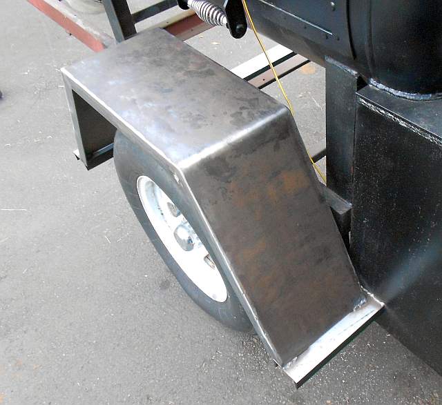
And here are a few pictures of the fenders after installation.
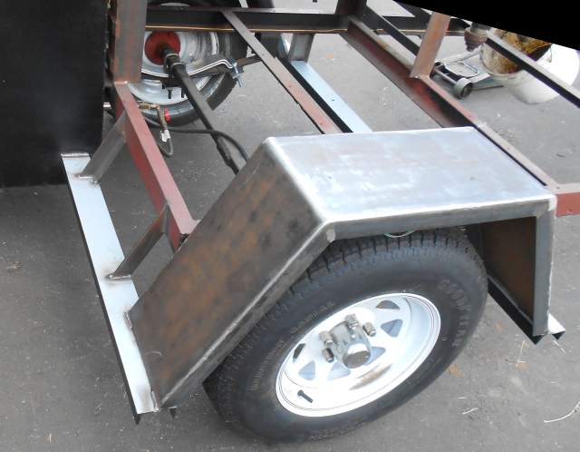
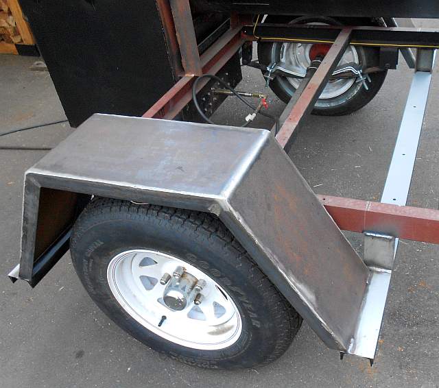
I used some scrap channel a neighbor had lying in their yard for fender supports. The flat parts sticking out beyond the fenders act like steps which help old guys to get up onto the trailer.
On the side of the trailer with the cooker, the flat fender top (10x18-1/2") acts like a table.
My goal always has been to have a fully legal trailer so I would never have to worry about getting pulled over or ticketed on the way to or from an event. I've owned trailers without fenders, lights or license plate before and always worried when I pulled them. Some simple sheet metal work yielded light mounts that go onto the rear faces of the fenders. I used an LED trailer light kit from Harbor Freight. I had never wired up a trailer before so I'm sure I missed some subtleties but here is how I did it.
First, I pulled the trailer wiring Y-harness through the tube attached to the trailer hitch. Then I drilled and tapped a 10-32 hole up near the hitch and connected the white ground wire to the trailer tongue. I used push-on channel clips to run the wiring harness through the inside of the trailer body channel. I drilled mounting and wiring holes on the front corners for the side marker lights. I prepainted the trailer frame and then installed the side marker lamps with their wiring sticking through the holes to the inside of the channel. Again I connected the white ground wires to the frame. Then I used quick-splice wiring connectors to electrically connect to the brown wires.
I used more channel wiring clips to run the trailer wiring down each side channel all the way to the back corners. I drilled holes through the trailer frame at the back corners. Then I set the fenders in place and carefully match-marked corresponding holes in the fender sides. After that, I installed the fenders. I drilled holes in the back face of the fenders and pulled the trailer wiring through and trimmed to length. (The trailer wiring is in a "Y" shape so it's easy to put half of them to each side of the trailer.) I cut about six inches of 1/4" shrink-wrap and slid it back down each wire bundle, pulling it through to the underside of the fender and working it through the side of the fender and through the trailer body channel until there was one continuous piece of shrinkwrap protecting the fragile trailer wiring as it went through three "walls". Then I used a heat gun to shrink it so it stays firmly in place. I drilled and tapped each fender for a ground screw. I used 1/2x10-32 brass screws so they won't rust away. I made up short white ground connector wires for each fender. I prepainted the fender around the area beneath the light mounts, except I masked off the weld areas.
Here you can see the back of one of the fenders, prepainted, before the light mount was welded over the area. The picture shows the blue heat shrink that runs through to the underside of the fender, out the side of the fender, and through the side channel of the trailer body. Also you can see the crimped-on electrical fittings as well as the short white ground connector wire.
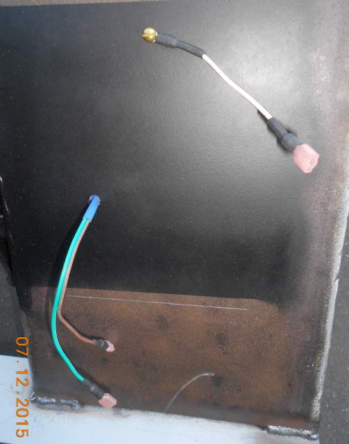
With the LED trailer lights mounted on the prepainted light mounts and the wires sticking through the back, I stripped the wires and crimped on faston connectors. I used shrink wrap to help keep rain and snow out. The idea was to install connectors on all the wires, then fit the light mounts and weld them on, and then connect the wires without too much trouble. Then I can finish painting the outside of the fenders, having already painted the light mounts and the area masked by the light mounts.
Here are the trailer lights on their light mounts before they were welded to the fenders.

To install the light mounts, I just moved the wires out of the weld area and welded them in place on the fenders. Then I painted the fenders. This trailer came with a title and license plate. When I bought tabs this year, I also bought a new license plate from the state. I chose a 4x7" motorcycle-sized license plate because it fits nicely on the 10" wide fender. I installed the plate under the left light so it will be illuminated at night. I used 10-32 stainless truss-head screws. (Truss heads are extra-wide so they don't need a washer.)
Now my smoker trailer is a legal vehicle. The lights work great and the fenders should last for years!

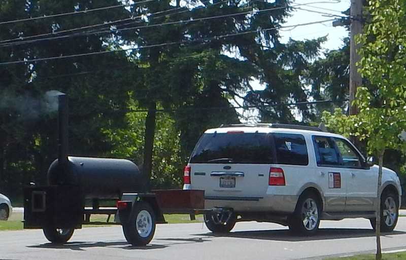
This cooker is an ongoing project. I did the spring reinforcing work and added the fenders, lights and license plate in the spring of 2014. I built this smoker, had some truly memorable BBQ parties and a ton of fun. However, time moved on, and I wound up selling this trailer-mounted smoker to a BBQ caterer from one state over. He was delighted with it. In fact, he called me about a month later and told me he wanted 4 more! I had to decline, sadly. Anyway, here she is being towed away by her new owner, still smoking as she rolled away.
Thanks for reading!