
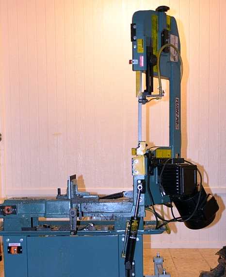
It happens that my buddy and I both own the same saw model, the Turn-Pro 7x12 gearhead horizontal/vertical bandsaw. We like the machines in general but have noticed some problems that stem from the machine's wheels as they came from the factory. Here is an old picture of my saw, all dirty, but you can easily see the fixed wheels:
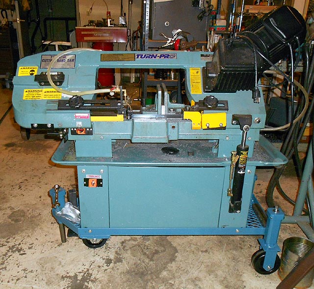
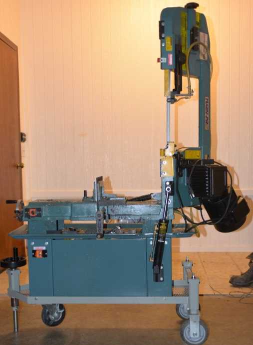
Anyway, my buddy scratched his head for a bit and came up with a design for a new bandsaw cart which addresses all of these problems. As you can see in the pic below, the rear casters are directly height-adjustable via jacking screws, whose protruding ends are milled square to accept a wrench. The front leg is also height-adjustable. It can be retracted to set the bandsaw front down onto a swivel caster. With 5" casters the saw is very easy to move. It is stable in all positions, easy to level, and the saw table is now at a much more usable 29". And finally, with 3 points of contact with the floor, the saw always sits solidly even on an uneven surface, like a 3-legged stool does. On its new base, the saw table is now a very usable 28", easy to match with infeed/outfeed tables.
The solid leg to the floor keeps the machine from moving (mostly). By extending the rear wheels out 5" it is much more stable in the vertical mode.
We didn't touch the cooling system. We pulled the cotter pins from the original axles and removed the wheels & axles, lifted the saw and put it down in the new base and bolted the base to the saw. The cooling system works better now in that with the saw level, the coolant drains correctly.
Sitting on 3 points, the machine can be leveled easily. Now not only does the coolant drain correctly, but it is easier to cut long stock square if the saw table is level side to side.
One more advantage - you can sweep beneath it now!
My buddy's idea originally was to have the cart on 3 casters, 2 fixed and 1 swivel, with the swivel being locking and swivel-locking as well. But in practice even a swivel-locked wheel felt very shaky, so he decided to use the front adjuster as a solid foot, with the swivel caster mounted inboard. This eliminates the need for an expensive large caster fitted with a swivel lock.
Enough about the problems. We believe this base design addresses all of them. The remaining part of this page will go into detail as to how we made the machine bases.
Here are my buddy's working drawings:

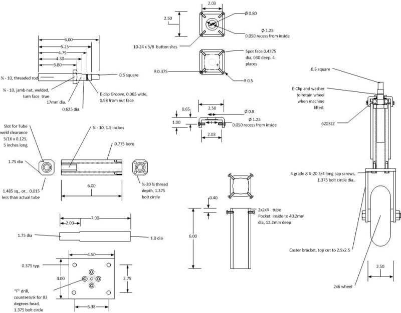
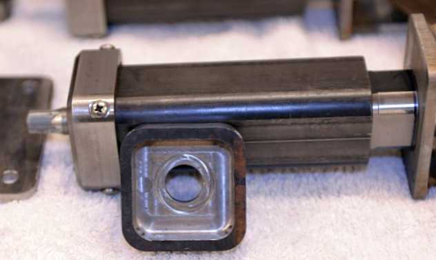
Hopefully you can figure out what's going on in those drawings. Anyway, here is a view of the saw base's front end, upside down. You can see that the square leg extends and retracts, and when retracted that the saw base will set down on the swivel caster:

Since we made two saw bases (for my buddy's machine and for mine) we had to make a total of six adjustable legs. Note that the caster plate is bolted to the bottom of the adjuster in the next image:

My buddy is quite the machinist. Look at the detail on the top cap:
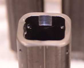
The top of the 2x2x1/4" square tube is counterbored for a bearing. You can see the bearing pocket:
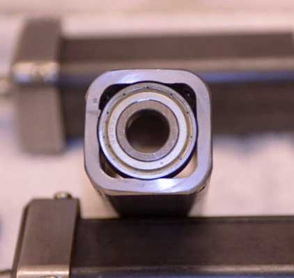
Here is a 6203 bearing in the pocket. In this case it just acts as a thrust bearing, to make turning the screw easier:
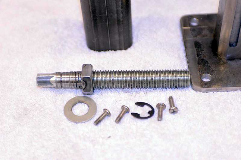
Here are the internal parts of the adjuster. The thrust collar is a nut welded to the thread, then faced true. The thread above the nut is turned to fit the bearing. The washer was bored on the lathe for a tight fit. The clip keeps the whole assembly together. My buddy chose 3/4-10 threaded rod for the adjuster screw. As you can see, the end is milled square for a handle:
Here is a set of three adjustable jacks assembled:
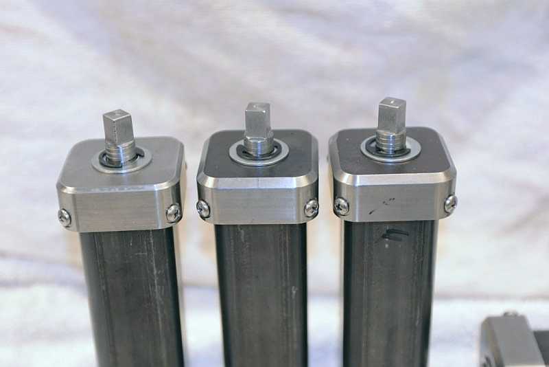
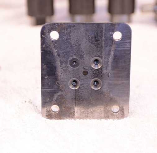
The front leg can be configured two ways. The pictures above have shown it with a solid leg. However, it is also possible to fit a caster plate to the bottom of the front leg, and attach a swivel locking caster with brake. (In the time I've been using my new saw base, I have never used this caster plate.) Here is what that caster plate looks like:
Here is a shot of an assembled front adjuster with the solid leg installed. The solid leg can easily be removed by pulling the pin and sliding the solid bar out. Then the caster plate is screwed directly to the jack shaft. With a height-adjustable front swivel caster, the bandsaw is super portable and can turn right around within its length.

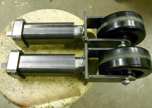
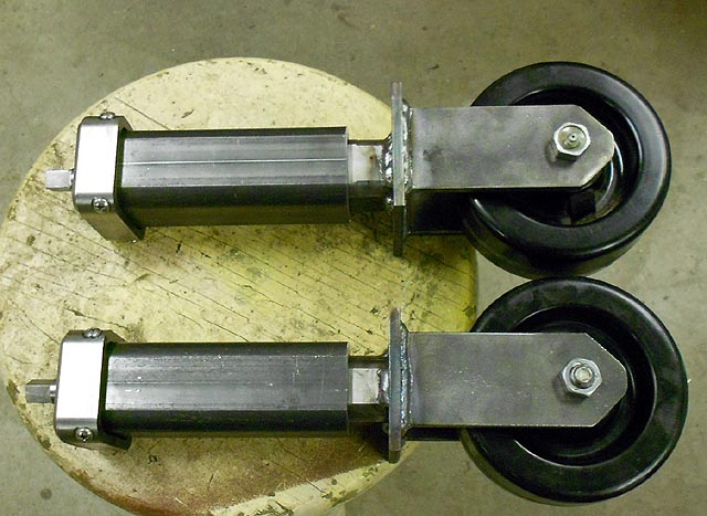
I chose to fabricate rear caster mounts, as rigid caster bodies are a simple topology to make. My caster bodies were more compact than the ones these wheels came with. Here are two images of my assembled rear adjusters complete with 5" casters:
Sadly, I don't have a picture of the fully assembled saw base before I put my saw on it. However, it's just a simple angle iron frame with two pieces in front cut to 45°. The adjusters are all welded to the frame. The saw base as built has a small amount of storage which comes in handy to store small objects related to the bandsaw's operation. I'll leave you with my as-completed photo. Thanks for reading!