In my pastime as an industrial hobbyist who buys/fixes/sells things, I often have to move heavy things around. Many of my projects are related to this activity. I have used engine hoists since I was a teenager back in the '60s, and I continue to own one to this day. There are a lot of limitations to the standard 2-ton import engine hoist, though. This is the reason many industrial shops instead use floor cranes. This article is about a very old floor crane made by Ruger. It came to me for free, but it was in terrible condition. As this story unfolds I'll cover the problems it had and how I addressed them. But first, I want to talk a little more about the limitations of an engine hoist.
There are some problems with engine hoists. First, they are very limited in their ability to straddle machinery, since their legs come close together towards the body of the hoist. Second, once you lift a load into the air, engine hoist casters are not capable of moving the load. Third, if the user is not very careful in setting up to lift a load over a ton (these are after all TWO ton hoists) it is very possible for the hoist to crumple and drop the load. I know - it happened to me! Finally, yes it's possible to lift the hook of an engine hoist way up, but to do that you have to extend its boom fully and in that position it can only lift 1/4 of its max load.
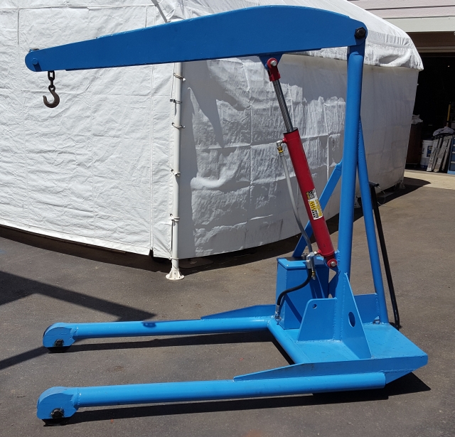
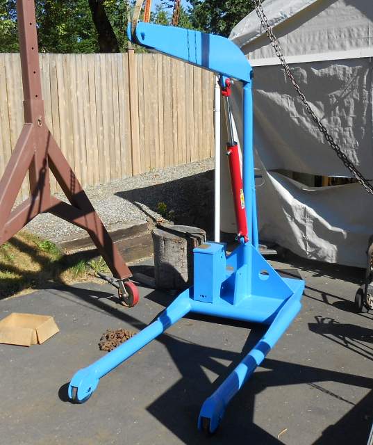
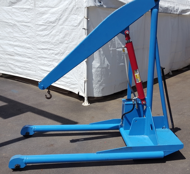
As you look at the picture above, you can see that the floor crane's legs are parallel, so if you can get the front wheels around a machine you can roll the crane all the way in. Second, although you cannot really see them, this crane has very sturdy 6" cast iron wheels that run on 1" axles with roller pins. These wheels have to be rated for at least two orders of magnitude more weight than engine hoist casters with their 3/16" pins and 2" wheels. Next, there isn't any setup to a floor crane. You roll it into place, you rig your piece, you lift. You don't have to fiddle around sliding booms and legs to their correct position. Finally, a floor crane can lift its full rated load all the way through its entire lifting range (not just 1/4 of its rated load). That all being said, let's tell the actual story.
I had an acquaintance who had a serious shop packrat syndrome. He must have had eight thousand pounds of machines, tools, equipment, materials and miscellany in his garage/basement and his six temporary garden sheds, not to mention sitting all over his lot. Sadly for him and his family, he suddenly became afflicted medically to a degree where he was clearly going to be in an institution the rest of his life. As he rented his house, this left his family with about two weeks to empty out his house. They hired two guys to do this. Let's call them Mutt and Jeff. Those two were a real pair to draw to. In the first place, they were homeless. They lived in a homeless encampment at least 20 miles from the place. For another thing, they knew *nothing* about electronics, machining, welding, or hardly any other shop practice. Since they were getting a percentage of the take, this to some strange conversations while selling. For example, I might go pick up a piece of a tool & cutter grinder and bring it to them (they had a multiweek every-day yard sale) and ask them for pricing. They would invariable ask me what the item was, how it was used, and also how they could look it up on the Internet to figure out its "retail used" price. Needless to say, the days went by and the clutter remained.
Eventually the time pressure forced Mutt and Jeff to abandon their ridiculous pricing model, and they started relaxing their standards. For example, in the beginning if I asked about something in one of the garden sheds, they would want to know all about that single item as I described above. Two weeks later, they'd say something like "Take the whole shed for fifty bucks." I thought that was more like it! Anyway, sitting outside in Seattle's midwinter rain was this ancient floor crane. Its nose drooped like a sad donkey's. The hydraulic cylinder's shaft was badly rusted. The rubber on the hydraulic hoses was badly oxidized and cracking. The crane had had modifications done with no concept whatever of cosmetics. I tried pumping on the hand lever and to my amazement it lifted right up. However, when I stopped, it came right back down. The first two or three times I looked at it, I just walked away from it without even asking about it. The last time I was out there, I was pulling a trailer and we were basically loading up anything we wanted, as Mutt and Jeff had abandoned all hope of extracting money and were just worried about making things disappear. So to make a long story short, I got it for free.
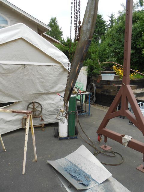
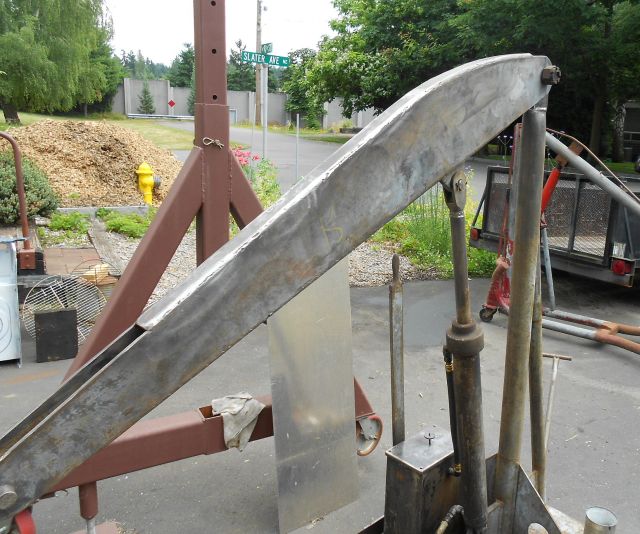
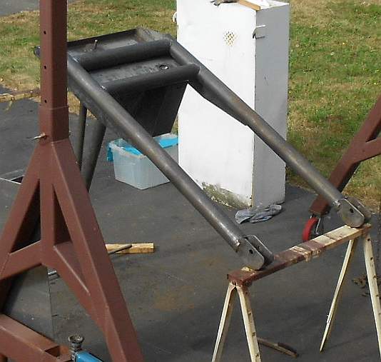
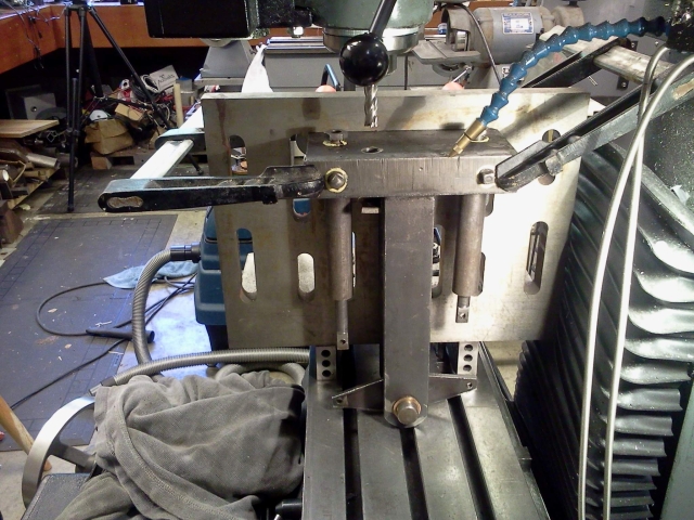
I should warn you that I didn't really document this project with pictures very well. For example, I didn't take a proper "before" picture. Here is the only picture I have that shows the crane before I really started working on it. But it already looked a lot better than it had just because I'd pressure washed all the grease and organic matter from it.
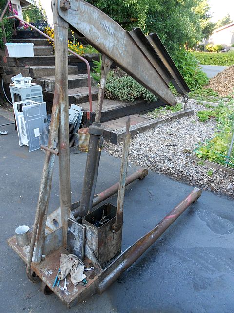
As you look at the picture above, take note of the pieces of steel channel welded to the top of the boom. Also note the abysmal condition of the cylinder. You can see the handle sticking up roughly parallel to the cylinder. To work the crane you push the handle back and forth. At the bottom of the handle you see what looks like an open olive oil can. That's the hydraulic reservoir. When I first took the top off (you can see the top leaning up against it) I realized it was chock full. As I began removing the fluid I quickly realized that only the top inch or so was hydraulic fluid - the rest was rain water! I realized that this floor crane was not designed to sit out in the rain. The cylinder's top cap isn't sealed around the shaft, so rainwater can flow in. Although it isn't visible in this picture, there is a hole in the reservoir top which isn't sealed either. Those two unsealed holes were how the system had filled with rain water.
It was during this initial examination that I realized that this machine, although professionally made by Ruger, today one of the pre-eminent manufacturers of floor cranes, showed signs of being built in extreme haste. A lot of parts had been torch cut and quickly welded with no cosmetic cleanup, I contacted Ruger and sent them a picture of the machine but they disavowed any connection to this machine. However, its nameplate didn't agree - it clearly said they did make it. I figure it was built during World War II, possibly for use in one of Seattle's shipyards which themselves had ramped production up to the point where Todd Shipyards was cranking out destroyers for the Navy every 3 days. Anyway, despite the unsophisticated manufacturing techniques, the machine actually had elegant lines to my eye. Of course, the effect was entirely ruined by the welded on boom extensions. Those had to go!
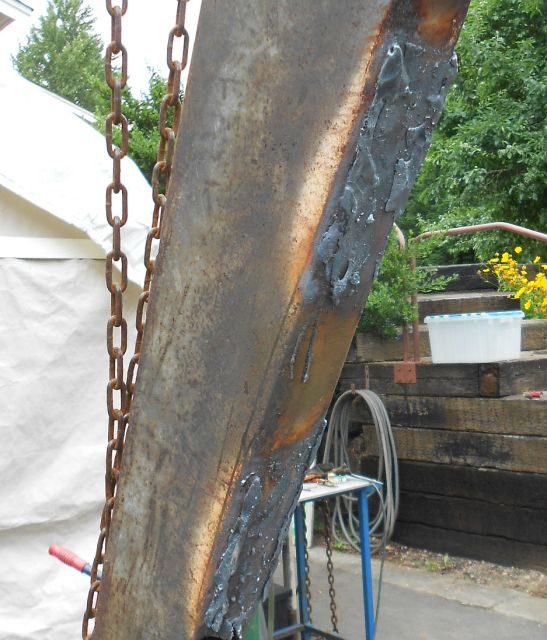
I was once a pretty fair hand with an oxyfuel torch, having worked in Seattle's shipyards for 13 years in my early life. My main tool during that time was a cutting torch. Anyway, as you can see above the first order of business was to hack off most of the ugly. This left behind a hideous mess of steel with a ton of weld metal. It would have taken many hours to grind it all away. So I dug out what I was taught to call a "flushing tip". Here is a picture of the tip I used:
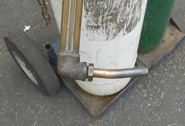
Such a tip has a huge oxygen jet along with a lot of preheat jets. When you pull the torch's trigger, the oxygen does not shoot out in a thin line like it would with a cutting tip. Rather, a big fat gust of oxygen flows out much more slowly and less violently. It is easy to start something melting and then gently encourage the metal to continue melting and run off the part in huge drops. It is not wise to let molten metal in globs that size land on asphalt! Anyway, here is a shot of my setup with a piece of aluminum positioned to catch the molten metal::
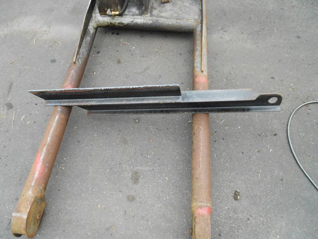
After flushing away most of the excess, this is what was left:
Next, I took a 9" angle grinder to what was left. Here is what the boom looked like after the heavy grinding:

The scars were still very visible, but the clean lines of the boom were beginning to emerge. Next I went over the area with a flap wheel, blending the scars into the base metal of the boom. Take a look:
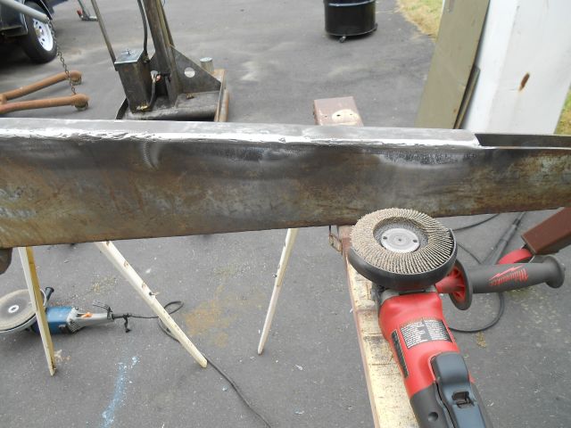
Quite an improvement! BTW this boom as well as the entire crane is made of 1/4" steel. Pretty beefy stuff, especially compared to a modern engine hoist.
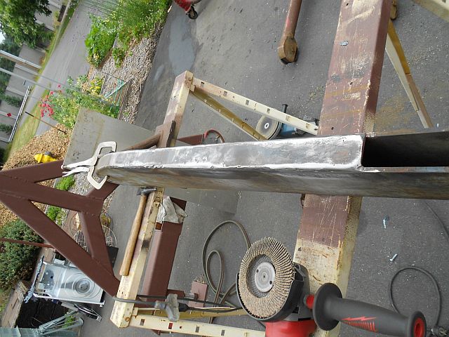
Here's one final shot which shows the boom restored to its classic lines. Also notice the old cylinder, still in place in the next shot:
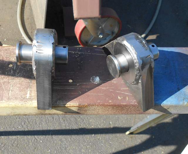
The next thing I did was to tear down the cylinder. What I found discouraged me to the point that I bought a new cylinder. By doing that I got one with a hard-chromed rod, plus it didn't need a rebuild. While I was at it, I had new hydraulic hoses made up and bought new fittings. The original cylinder's rod was much longer than the body. This nonstandard configuration would have been too expensive to replicate as it would have meant custom ordering a cylinder. The new cylinder was more than a foot shorter. So I repositioned it with new upper and lower mount lugs, shown here with new clevis pins:
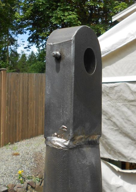
I fitted those in place and welded them up solidly before proceeding with the cleanup effort. To do this, I removed the boom. Here is what the top of the mast looks like - it's a huge chunk of solid steel! Nobody in their right mind would make something this way nowadays! At any rate, notice how the radius on the upper lug was cut with a cutting torch and the cut wasn't even cleaned up.
With the ugly modifications to the boom undone to the best of my ability, I moved on to cleaning up the rest of the machine. For anyone familiar with machinery rebuilding, the next bit is pretty standard stuff. It was easier to clean the metal when most of the paint was peeling off already. For most of the work on the crane's body I used an overhead gantry to position the crane so I could work in a standing position. Here is a much cleaner looking machine, sitting on sawhorses, still connected to the overhead hook:
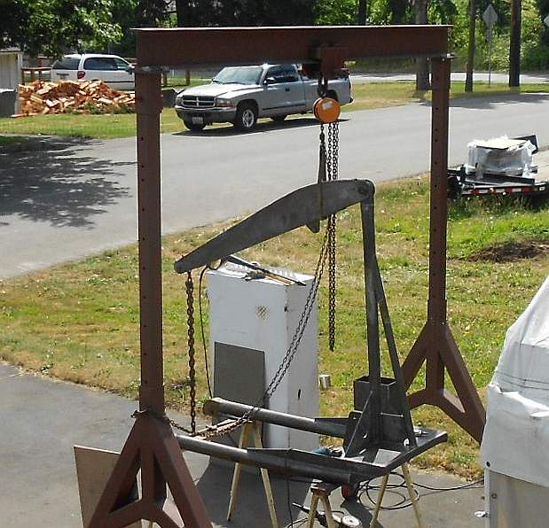
In case you were wondering why the boom didn't simply fly up when I lifted the hook, notice that the nose of the boom is chained to a stick that goes beneath the legs. It may be hard to see because the stick is lying right on top of the sawhorse, Anyway, it lifted, believe me!
After I got the top of the crane body all cleaned up, I turned it over and cleaned the bottom:
With the boom entirely scrubbed clean, I started painting. Here's the bottom with paint on:
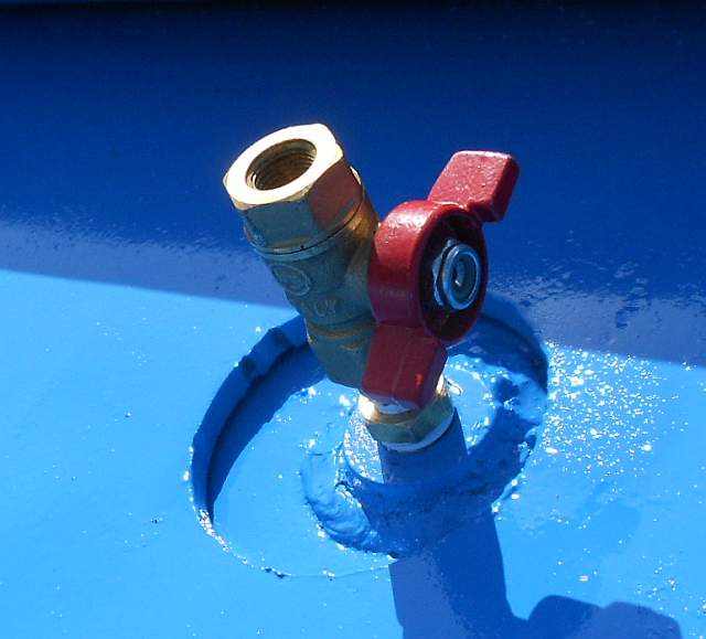
Remembering the pain of getting all the fluid out of the hydraulic reservoir, I was somewhat abashed to find a drain plug in the bottom. With the bottom up and all painted, I added a proper drain valve so I could just reach underneath and open the drain if needed:
After that, I tore down the casters. The steel pins that act as roller bearings were quite rusty. I removed the rust and polished those with a small vibratory tumbler. While that was going on (the tumbling took several hours) I cleaned and painted the wheels:
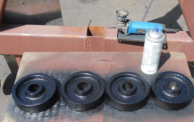
After I got the wheels all back together, I reinstalled them on the crane and turned the crane right side up and finished painting it. I also painted the boom and reassembled it:
That completed the cosmetic restoration, the part that shows. The next step was to move on to repairing the hydraulic hand pump unit.
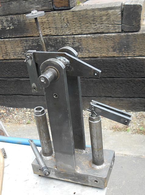
This hand pump hydraulic unit isn't much to look at but I learned a lot working on it, and it certainly has the virtue of simplicity. Let me see if I can talk you through this. At the top of the unit is a horizontal shaft (running front to back in the picture). This shaft is supported on both sides by bronze bearings in vertical legs. The shaft is welded to a rocking arm which connects via links to the tops of two pistons which travel in vertical cylinders. The cylinders aren't very fancy. I don't even think they're machined on the inside. There are no rings. The piston is comprised of two pump leathers back to back, screwed to the end of the piston shaft. You can see the piston shaft and cup leathers on the left side of the above picture (the pump leathers are at the near end of the piston in the picture, where they look like rubber). With a long lever attached to the shaft, the rocking arm goes back and forth and the pistons go up and down.
The base of the hydraulic unit is another large flame-cut steel block. The whole hydraulic unit is screwed to two sides of the reservoir, a bit above the bottom so there is clear space underneath it. In use, this space is filled with hydraulic fluid at atmospheric pressure. Below each cylinder, on the bottom of the block, are check valves. As a piston rises, the pressure drops behind it. This lets the hydraulic fluid in the reservoir push the ball on the check valve up, allowing fluid to flow into the cylinder. When the piston goes down, on the other hand, the check valve closes and the pressurized hydraulic fluid flows out a horizontal passage and up to the crane's cylinder. The boom goes up both on the push and pull stroke of the long lever handle.
Behind the left end of the rocking arm you can see a vertical threaded rod with a knurled handwheel on the top. When that rod is screwed down, it bears on the ball in a third check valve. This check valve only goes to the pressurized passage - not to the reservoir. So when the ball is pushed down (by screwing in the vertical rod) the fluid in the cylinder can flow back into the reservoir through the check valve and the boom lowers.
Lot of writing, but it's quite a simple unit. When I got it, it had two big problems. First, the pump leathers were completely shot and disintegrating. Second, the load holding check valve no longer worked. As I said earlier, I could pump the load up, but then it would come right back down. Each of these problems proved to be challenging to overcome. Before I get into that, though, I want to show you a few more views of the hydraulic unit.
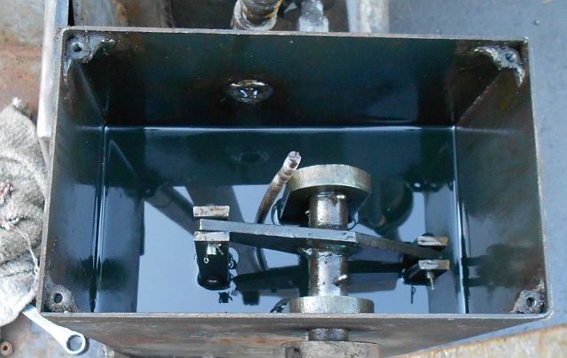
Above is what I saw when I took the top off the hydraulic reservoir. I had to remove the knurled thumbwheel, but after that the lid came right off. Looking down, you can see the rocking arm connected to both piston rods. You can also see the vertical load release valve shaft, the somewhat bent vertical rod threaded on the top. You also see what looks like old hydraulic fluid, but of course it turned out to be a small amount of hydraulic fluid floating on top of a larger volume of rain water.

You can see quite a bit in the picture just above. The load release check valve is disassembled and the parts are set out on the tuna can so you can see how they work. To the left is a pipe plug. The check valve is installed from below, but the fluid inside can not go out the bottom back to the reservoir because that hole is plugged with the pipe plug. There is a spring which fits inside the pipe plug and bears on a ball. The ball pushes on a hole which is smaller than the ball. When there is pressurized fluid behind the ball, the ball is forced against the smaller hole quite hard, and seals the passage. Unless, of course, the ball is pushed down with the load release rod, also visible in the picture. Finally, you can see the pump leathers on the end of the piston shaft just above the ball/spring setup.
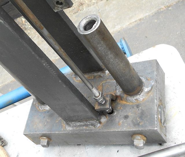
This picture shows exactly how the load release check valve rod works. There is a piece of flat steel bent into a Z shape and welded to the base. It is threaded, and the rod screws into it. The pairs of jam nuts are there to keep the operator from accidentally screwing the rod too far either way, which would cause undesirable things to happen.
As I mentioned above, the check valve ball no longer seated cleanly in its hole, so the check valve didn't work. The only thing that made sense was to recut the valve seat so a new ball could seat properly. This sounds simple but it actually took a fair bit of fiddling to set the unit up on an angle plate on the table of a Bridgeport mill to do the few seconds of needed machining.
Even with a freshly recut valve seat and a new chromed ball, the check valve still didn't want to seal. I took the unit to see the pros at Universal Repair Shop on Boylston Avenue East on south Capitol Hill in Seattle. I've been going to those same guys for over forty years. Back then, that area of Seattle was like Auto Row. Nearly all the businesses were auto repair or sales-related in some way. Now they're all alone and they mainly survive by rebuilding power spray painting machines. But they know *everything* about small hydraulic things. I cannot recommend them highly enough. Here is a link to their Web site. Anyway, they were very interested in my primitive old hand hydraulic pump. When I showed them the check valve that didn't work, they howled with laughter. They told me it was going to be a holy bitch to make a ball that large seat properly. They told me to use a soft drift pin to hit the ball, driving it hard against the seat. So that was the one trick I learned from them - drive the ball sharply against the seat. I should mention that I tried one other thing as well. The chromed balls are 0.500" diameter. It so happened that I had a tooling ball in my junk box, which was a 0.500" ball mounted on a 1/4" shaft. I used the tooling ball plus some valve grinding compound and lapped the leaky valve seat. I cleaned up afterwards with carb cleaner and compressed air.
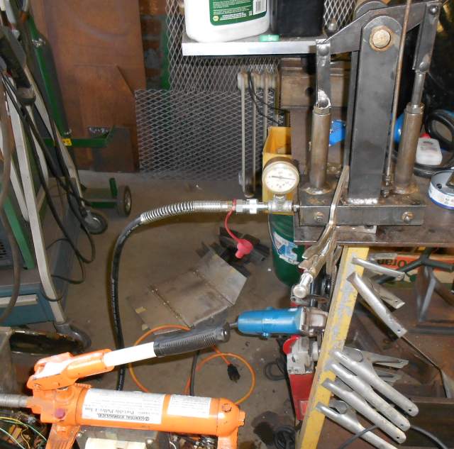
I connected a hand hydraulic pump to the pressure passage in the base block (see above). Fortunately, the two check valves at the bottoms of the vertical cylinders worked correctly. This allowed me to simulate a load on the boom by applying hydraulic pressure, to see if the load retaining check valve worked.
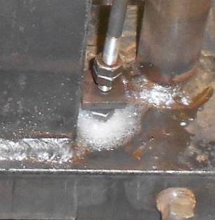
Over and over again, the valve kept leaking. You can see the fluid bubbling past the ball in the image just above. I'd tear down the test setup, tear down the check valve, and whack the bejesus out of the ball, then put in another new chromed ball. Then I'd reassemble everything and test again. After several iterations I was ready to throw the damn hydraulic unit in the dumpster! Finally, one time the valve held! I think the ball seating method (hitting the ball against the seat) took a lot of repeating because there was so much metal to deform, the ball being so large. Eventually, it worked, hooray!
On to the next problem. To replace the pump leathers, I turned to the guys at another of my favorite industrial vendors, Omni Packing and Seal in South Seattle. Here is a link to their Web site. As you can see from pictures above, these pump leathers are little cups of oiled leather. Mine were a highly nonstandard size. To get 4 new ones I had to do a custom order. Their price was reasonable, about $6 per part. Only problem was they had a 10-part minimum. So I have a set of spare leather cups, itself with a couple of spares in case I lose 2, LOL! Here is a closeup of the six pump leathers I didn't need:
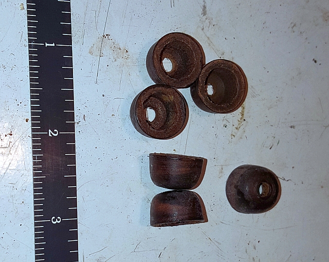
There isn't all that much to them. The manufacturers take a certain type and grade of leather and soak it. Then they punch the center hole and then force the softened leather circle into a die, using an appropriately sized round-end punch. Then the leather is allowed to harden. Then they trim it to just the right length leaving a clean edge. Pump leathers are very forgiving. They can seal on bores worn out of round, or bores that weren't machined. Hand tire pumps use pump leathers. They are an old-school technology still useful today.
At any rate, with the refurbished check valves and the new pump leathers, the hydraulic unit was back in business. The last thing to do was to reinstall the hydraulic unit into the reservoir. I got bogged down and lost momentum at this point in the project. In fact, the whole project slipped to the back burner, then completely off my radar for over 2 years. But I eventually returned to it. I temporarily installed the hydraulic unit,then used feeler gages to measure the needed gasket thickness. I measured that it needed gasket stock .020" thick. It turned out that I had a roll of .015" gasket paper. I made gaskets and stuck them to the unit with blue form-a-gasket (a very light coating) and installed the hydraulic unit. I pumped it up and let it down a couple of times to bleed the air, then lifted a load and left it up in the air. I was pretty excited to see later that the load hadn't moved and best of all that there were no leaks!
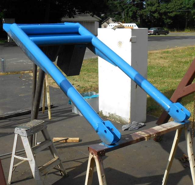
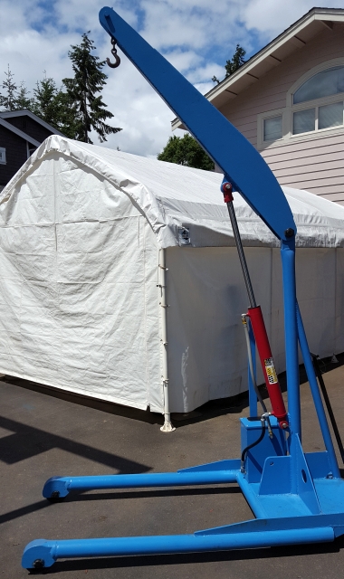
Here are a couple of pictures of the crane with the work completed. In the first picture, the boom is as low as it goes. (However, it is easy to use a longer 3/8" chain if you need the hook lower.)
And here is the crane with the cylinder fully extended. I'm not sure exactly how high the hook goes but it's at least eight feet.
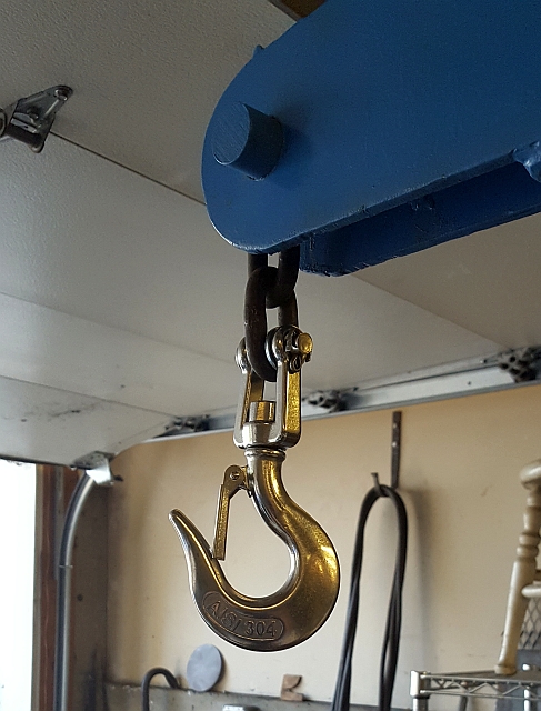
A few months after I finished the work described above, I found a swivel hook that is a great fit for this shop crane. It's rated for 2240 pounds, and it attaches directly to 3/8" hoist chain via a clevis integral to the swivel. It only cost $16.48 including shipping from the other side of the world, and it's made of forged 304 stainless. I couldn't be happier with it. Here's a final pic:
Before I wrap up, I wanted to mention that my total cost for this floor crane including the new hook was just under $250. I wanted also to publicly thank and acknowledge my friend and machining mentor Andy, aka lakeside53. It was his Bridgeport that recut the problem valve seat.
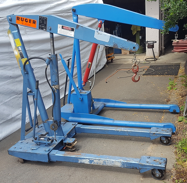
Update as of 2019: I spotted an ad for a Ruger straddle floor crane rated at 4000 pounds. I whizzed out there and grabbed it. I knew it had some issues. It leaked hydraulic fluid and the paint was degraded so there was some rust. So I brought it home. Here it is next to my old one:
Why bother? There are several reasons. First, the hydraulics are two speed, so you can crank the boom up rapidly until it meets resistance, then switch it to low speed and pump it with power. This is a major usability upgrade! Second, the legs straddle. That means I can pull two pins and pull the front of the legs away from each other so the crane can surround a wider load. To compensate for the angle, the front casters are adjusted so they are still parallel, so the crane rolls normally. This is also a very big deal. The knock on the inexpensive import engine hoists is that their legs are too close together so you can't get it up next to what you need to lift. The straddle feature largely solves that problem. Third, the floor crane is fitted with a floor lock. If I step on the pedal, a spring in the floor lock pushes a foot against the ground. It doesn't lift the crane off the ground but it does keep it from moving. A quick tap with my toe and it retracts.
Anyway, in the summer of 2022 I got tired of the issues and tore it down for rebuilding, derusting and painting. I will add to this page when that's done.
Thanks for reading!