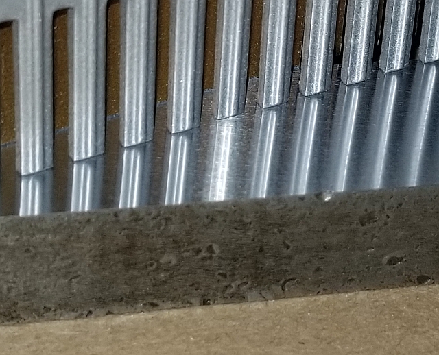
As part of my effort to eliminate ripple in the parts I ground with my surface grinder, I decided to balance the wheel. This page briefly describes the way I balance wheels and how I made the parts. Precision balancing the wheel is necessary for a good finish but not sufficient. But it's pretty key.
Much has been written about balancing grinding wheels. Most of these methods involve a balancing stand and arbor. Some remove material from the heavy side and some add material to the light side. Many methods involve balancing a wheel on its wheel adapter. I haven't seen one yet that acknowledges the reality that the grinding wheel bore is always larger than the wheel adapter spindle. It has to be, because as the spindle heats up, if the wheel were tight to the spindle, the wheel might break. Further, I believe many surface grinding wheels now with a nominal 1.25" hole actually have a 32mm hole which is 1.26", ten thou bigger. If you take a wheel that was balanced by for example drilling divots in the heavy side, and you put it on the wheel adapter, how do you know it is centered? And even if you know it's centered, how do you know it won't move on you during grinding?
Some methods involve drilling a bunch of holes around the edge of a balancing device. During balancing, weights are added to holes on the light side until balance is achieved. This seems OK until you realize that grit is going to pile up in those holes. Will the grit necessarily be balanced? I don't think so.
My method isn't original, novel, or patentable. It's easy to make and relies on simple laws of physics to balance the grinding wheel. Once my device is attached to a wheel adapter, it will automatically balance any wheel mounted on that adapter. Were the wheel to shift a little on the adapter during grinding, my device will very rapidly self-adjust to bring the wheel back to balanced.
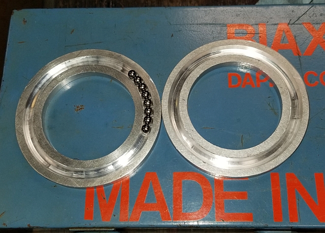
Basically I make a donut with a round tunnel in it. In that tunnel are chrome ball bearings that are free to roll around the tunnel as they see fit. The technical term for such a round tunnel is a torus. Anyway, you will understand when you see the pictures.
How can balls like this self-balance? A system will revolve around its center of mass. If the system is balanced, its center of mass is aligned with the designed axis of rotation. If the system is unbalanced, the center of rotation will be off center. There will be a heavy side and a light side. The heavy side is closer to the actual axis of rotation than the light side. The balls want to move according to centrifugal force to get as far away from the center of rotation as they can. Thus they will migrate towards the light side, thus balancing the system. When I turn on my spindle, I hear a very brief rolling noise as the balls realign to balance the wheel. Way less than a second. Once balanced, the balls will no longer move.
How I make my autobalancer is simple. I cut out a couple of pieces of aluminum larger than my target OD. I use a drill press with a center drill to put a center hole in each part. I put on my lathe faceplate and install a live center in the tailstock. I put a flat piece of wood next to the faceplate, and then the aluminum piece, and push the live center into the center hole so that it keeps it all together. I use a HSS trepanning bit and trepan out my two circles of aluminum. If I'm careful about this and don't touch the cross-slide between parts, they come out the same size.
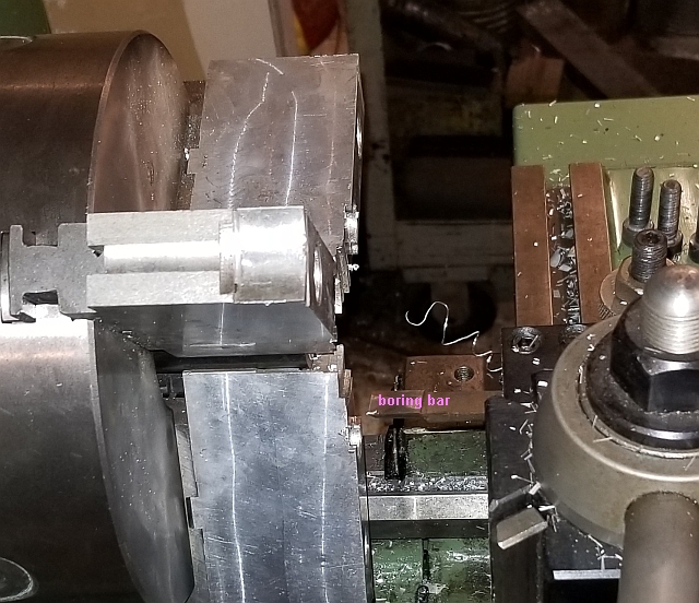
Next, I remove the faceplate and install my 3 jaw chuck. Then I put soft jaws onto the chuck, and carefully bore them to just fit the OD of my parts.
Here I'm boring the soft jaws to size. The boring bar is kind of hard to make out so I labeled it.
Now I can grip each part by its OD and it will be centered accurately. Once a part is mounted in the soft jaws, I drill it and bore it to a press fit on the outside of my wheel adapter. Since different grinders use different wheel adapters, I will not be providing any exact dimensions.

After the parts have been bored to size, I use a 1/4" HSS bit onto which I have ground a round end with 1/8" radius, plus cutting relief. I choose a convenient radius and plunge the form tool into the part 1/8", forming half of my hollow torus.
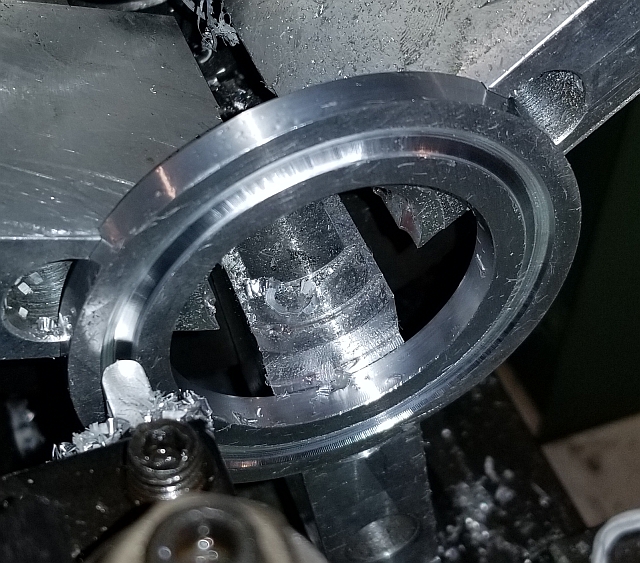
Both parts have the groove machined into their faces. I use 7/32" chrome bearing balls, a very loose fit in the 1/4" diameter "tunnel".
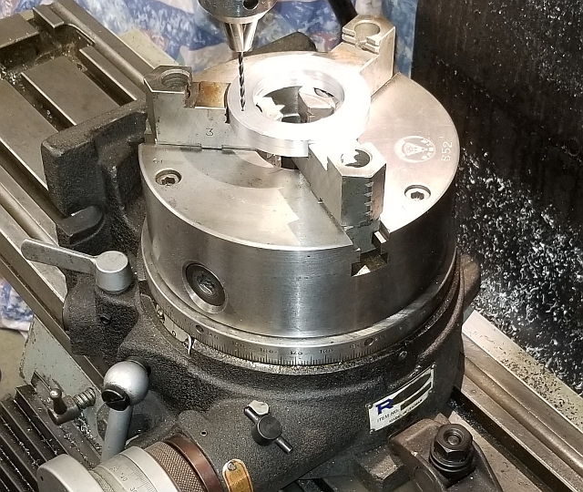
I drill and ream 3 holes equally spaced around the edge. The super spacer makes indexing 120 degrees easy. The holes are machined with the balls inside.
I press the pins into the reamed holes right on the mill. Three ground dowel pins are enough to hold the autobalancer halves together. There is very little force applied to the device in use. With the autobalance assembled, it is pressed onto the rear flange of my wheel adapter.

That's it! Now any grinding wheel I install on that wheel adapter will automatically be balanced. It really works!
As I said before, balancing your wheel will help you along the way to achieving a fine finish. It is also important to choose the right wheel and to dress it the right way, using the right diamond. I find it necessary to dress both the face and the sides of the wheel. How you grind, i.e. how fast you travel, how far you step over, and how deep a cut you take for roughing and finishing are also critical.
These are some of the procedures I am learning on my way to becoming an experienced grinder hand. I still consider myself a beginner. Maybe my little autobalancer can help you. They're fun and easy to make.
Thanks for reading!