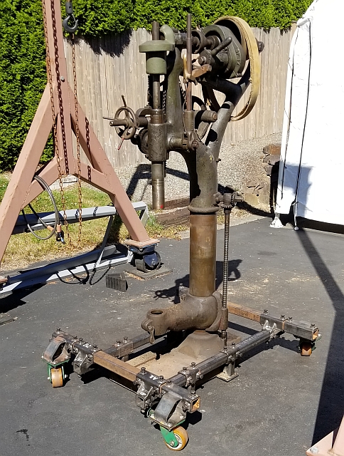
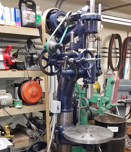
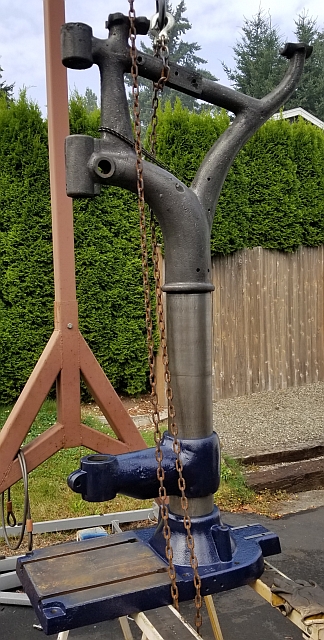
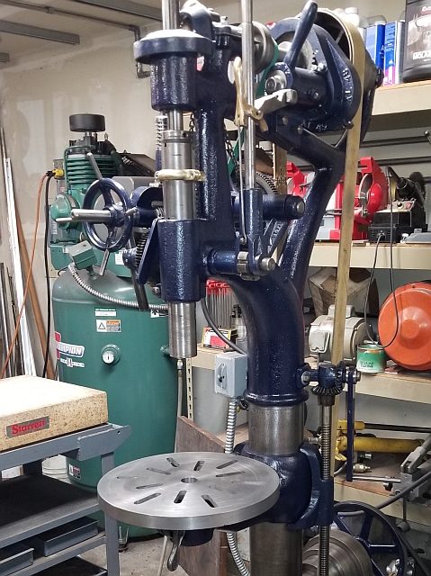
As I write this it is early January 2021. Last year was the Covid pandemic, and we were under orders to shelter at home much of the year. I decided to do another machine restoration to fill the time. A friend of mine recently acquired a Barnes drill press of the camelback style. I was very taken by it in person and resolved that someday I too would own one of these old machines. Above are pictures of the machine I bought locally. The left picture is how it looked when I got it and the right picture is how it looked after I was done restoring it. This wasn't just a "rattlecan restoration" - I did quite a bit of work on the machine and substantially improved its performance as opposed to when I got it.
I should mention that the "before" picture above does not show the table nor the lower drive pulley assembly, both of which were removed to make moving the machine simpler.
When you stand next to this machine, it looks very complicated. The best way to attack a resto job is to remove and restore one subassembly at a time. These subassemblies are very modular and easy to work on in isolation.
The techniques I used are not new or groundbreaking. I have used them many times. For removing paint and rust I use an angle grinder with a variety of wire brush attachments. For heavy accumulations I use a pneumatic needle scaler. To remove most of the accumulation of oil and swarf, I often start with a pressure washer. In this case, to remove ancient packed-in chips coated with oil and rust, I used a pneumatic air chisel. Using combinations of these techniques I can bring parts to a clean and reasonably shiny condition ready for priming and paint.
I began with the lower flat belt pulley assembly. This machine is from the days when machine shops had overhead shafting and drove everything with long flat belts. There being no chance of me duplicating that environment, I removed the flat belt fast and loose pulleys and added them to my collection. This photo was taken during the initial move, while the machine was still on my little trailer. The pulley assembly is still bolted to the machine, but everything has a patina of dirt, grease and rust.
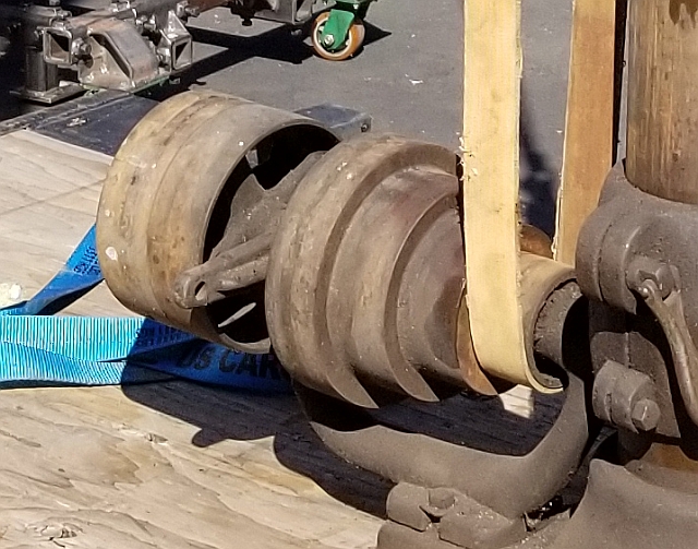
I unbolted the assembly and took it apart, freeing up the drive belt. I considered just cutting the belt, since I was sure I'd be replacing it, but for some reason I didn't. The upper part of the assembly has bearing caps with poured babbitt bearings. These were lubricated via holes in the top cap. Unfortunately open holes facing up just behind a machine of this nature are bad news, as they collect a lot of junk over the years. I ordered some oil cups with spring-loaded tops. I chose a fairly dark navy blue paint. This is what it looked like clean and painted:
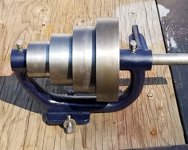
Quite an improvement, eh?
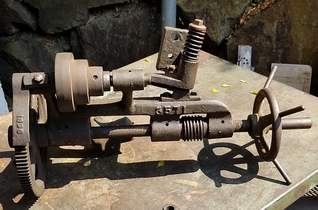
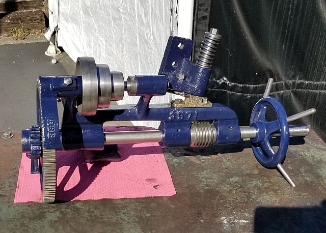
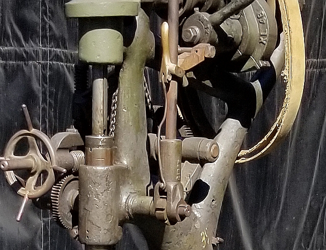
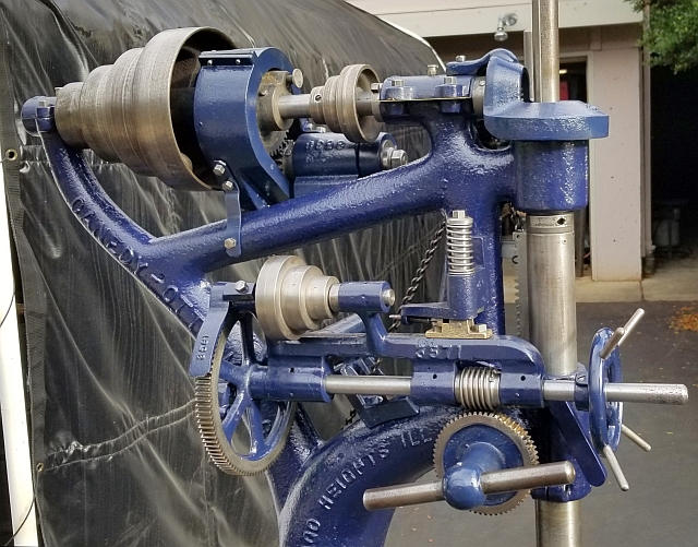
I probably chose the next subassembly because it was up at chest height, easy to work on. Here are images of the power downfeed assembly before and after:
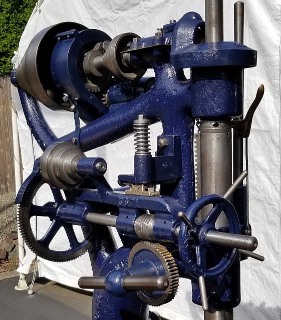
See if you can identify the power downfeed assembly in this next shot:
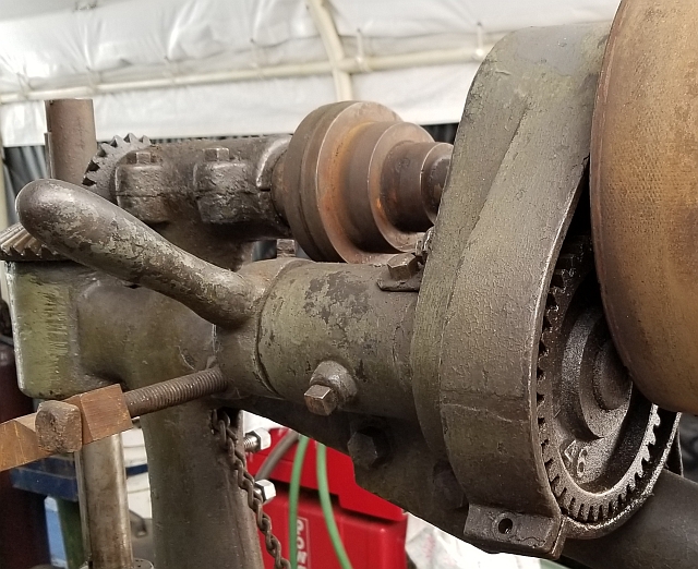
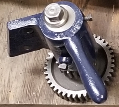
The next bit I worked on was the backgear assembly. Here it is still on the machine:
And another pic of the backgear assembly removed before I started cleaning:
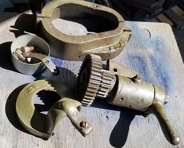
I didn't get a picture of the backgear assembly cleaned and painted with its covers. Here is one without the covers:
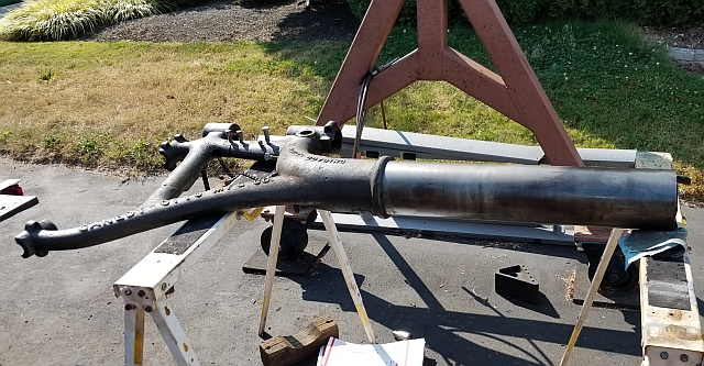
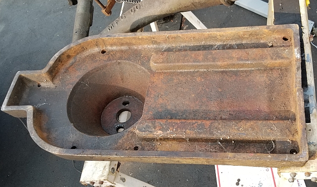
I don't have before/after pictures for every subassembly. After I finished with the lower drive pulley and backgear assemblies, I removed the top shaft and quill from the machine. I also removed the hand lever cross shaft. After that, I took the machine outside and set it on sawhorses underneath my gantry crane. I removed the elevating screw assembly and the main base casting and finally the table support casting. Then I was able to clean the stripped casting and begin to polish the column:
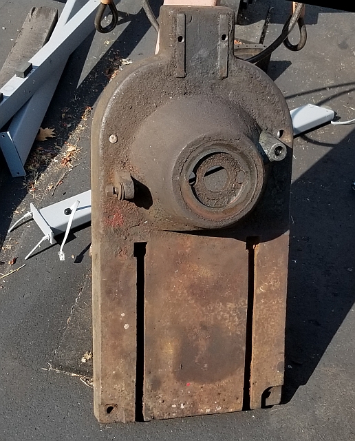
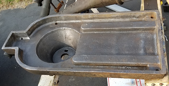
The drill press base casting, both dirty and clean:
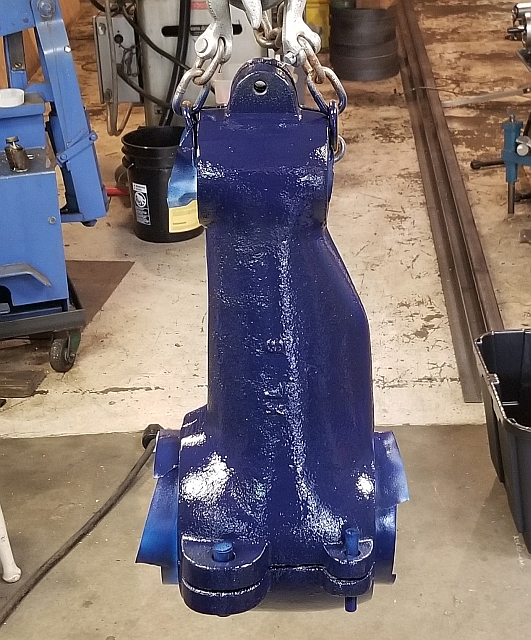
Here are some shots of the table support casting both during cleaning and after painting.
With the column and base and table support castings cleaned up, I started to reassemble the drill press. Here it is just after I bolted on the base casting. Having an overhead lift was enormously helpful during this project!
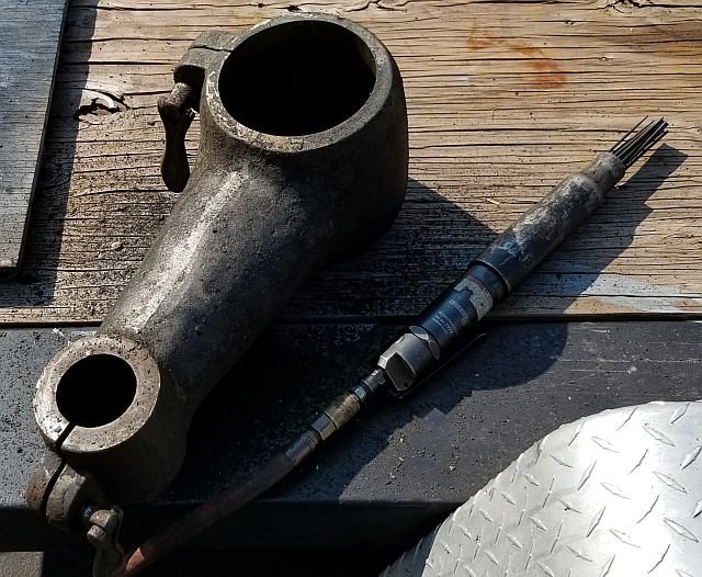
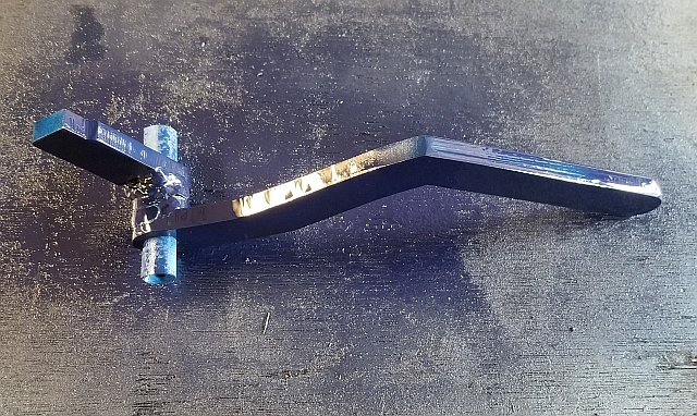
I believe that next I cleaned the top shaft plus all of its fittings, the quill and all of its fittings and covers, and the hand lever cross shaft along with the squeeze release lever for the feed arm. The rod beneath the squeeze lever had somehow gotten quite bent up over the years. See:
It's amazing what a hammer and a bench vise can accomplish!
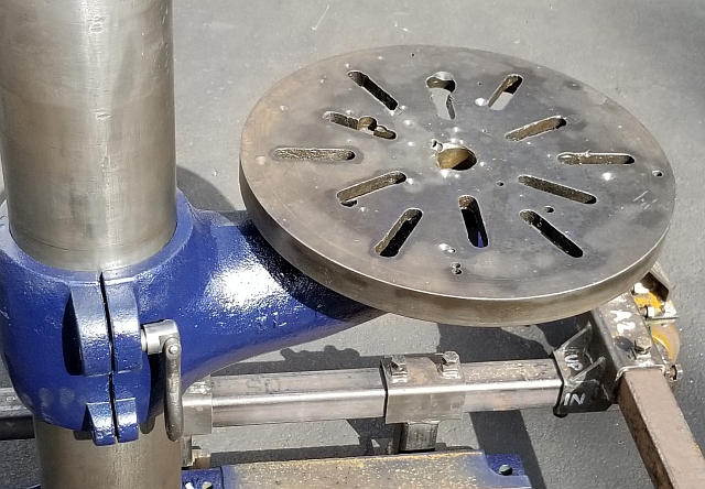
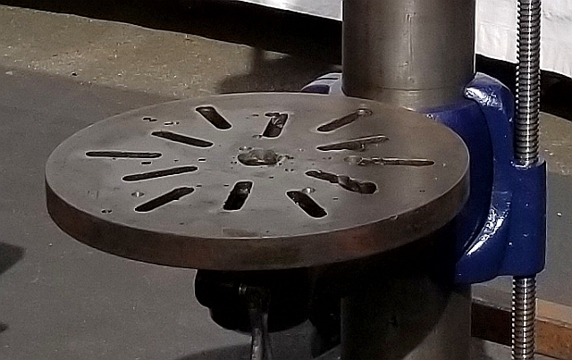
Like every drill press I've ever restored, the table on this one was overdrilled. Not terribly, but far worse than I was willing to live with.
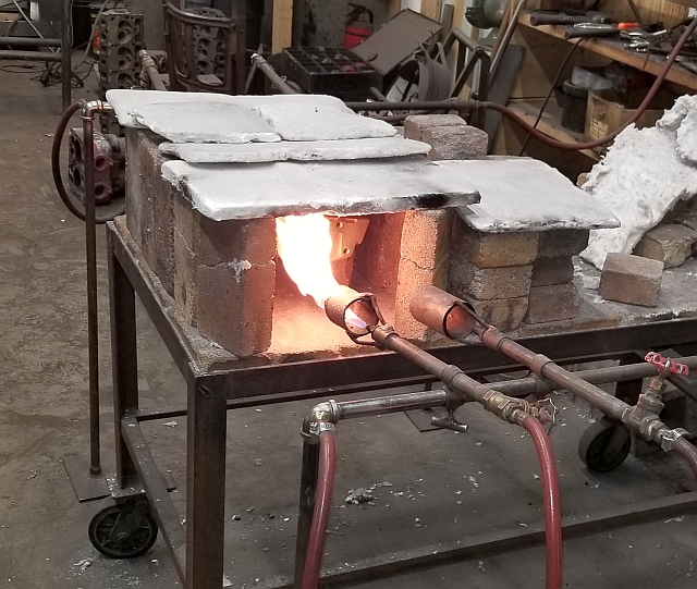
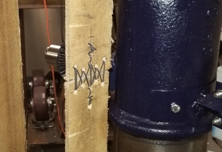
I have been taking cast iron parts to a local repair guy for decades. I believe guys like him are a national treasure. He works the old school way, heating castings slowly in a firebrick furnace. When the casting is up to temperature, he uses an oxyacetylene welding torch and cast iron rod and flux and gas welds the casting up. After, he buries the casting and lets it cool very slowly. Then he does finish grinding and cosmetic sandblasting. I don't have any pictures of him actually welding, but here is a shot of his preheat setup:
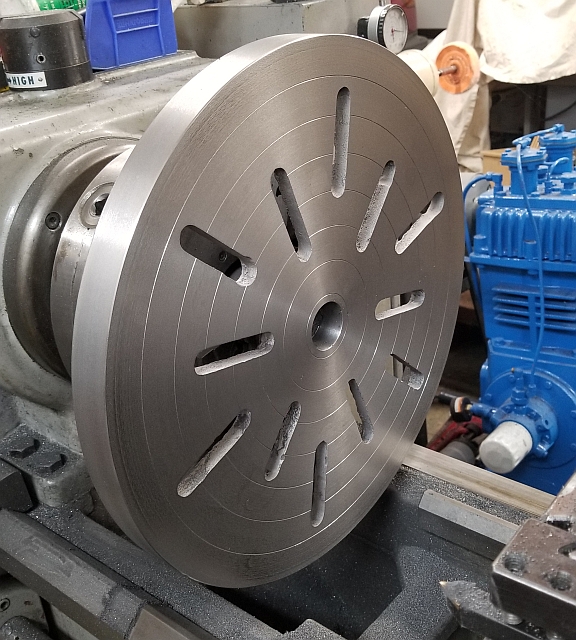
After the table was welded up, I prevailed upon a friend with a big Howa lathe to remachine the table. By the way, in my opinion, this is the only true way to restore damaged cast iron. Here is the table on the lathe and again installed on the machine:

This drill press is equipped with power downfeed. It is driven by a small flat belt from a 3-step sheave on the top shaft to another on the powerfeed shaft. I did not have this belt as it was missing when I got the machine. After some research, I carefully measured the belt length and ordered a belt from Al Bino. Al Bino is a curious name for a vendor of flat belts, but vendor they are, and the belt they sent me appears to be tight enough but not too tight. I wish it weren't green, though.
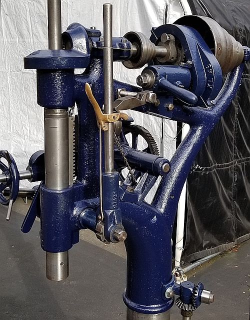
There is supposed to be a collar on the quill which has an arm that sticks out to the left. It was missing. That arm travels down with the quill. When the arm hits a lever I call the kickout lever, it releases a spring which lifts the powerfeed assembly up and away from the pinion gear on the hand feed cross shaft, stopping the power downfeed. That lever was there but it had shattered leaving only a stub. With some help from guys on practicalmachinist, I had enough information to fabricate a replacement. It fit perfectly and has worked great since. It's great to be able to weld small things sometimes!
That still left the problem of the missing stop collar. One guy suggested using a muffler clamp. That's not how I roll. I borrowed actual parts from a guy in California who was kind enough to mail them to me, and gave them to a buddy who drew them up in CAD, adjusted for shrink and 3D printed them. I had them cast in 93200 aluminum bronze, which is more difficult to machine but is nearly as strong as steel. Here's a picture of the bronze stop collar I had poured along with the 3D printed patterns:
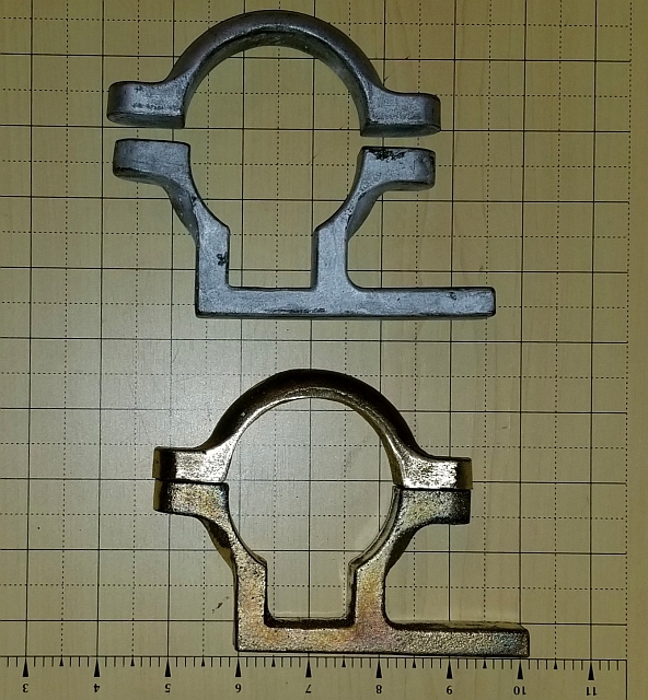
I'm no pro at machining raw castings. And (as you can see) I like to write up my projects. I wrote up a little piece on how I machined the stop collars.
Before I could test the machine I had to both add a motor to it and find a usable drive belt. Above I described working with the company Al Bino to get a smaller flat belt. I priced my main drive belt in leather and got sticker shock. I decided to trim mine to length and learn how to lace belts. After all, the book "How To Run A Lathe" by South Bend does have a great drawing on how to lace belts. Anyway, I had another machine I'd done recently which I wanted to convert to a DC motor so I "borrowed" its AC motor. I had a big sheave in my sheave drawer I'd been wanting to use up, and I had a brand new Gates B46 belt I bought for a different project but couldn't use because it was the wrong length. I had saved it for a few years and I was darned if I wasn't going to make it work on this project.
I found a piece of 3/8" plate and mocked up my power scheme. (Note, in the following picture there isn't a way to tension the belt so it's just sitting on there.)
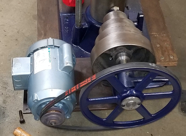
The mockup seemed acceptable, so I drilled the holes and installed the motor and lower pulley mount on my new motor mount plate. I tried the original drive belt at this point and it was way too loose. So cutting it to size was the next job. I went with my daughter to the fabric store and got some strong-looking waxed linen thread, cut the belt, punched some holes, and just went ahead and laced it up the best I could:
This belt is much tighter and seems to work. The lacing may not hold up, but that would be a problem for the future. For now I was almost in business. But my motor needed a proper motor switch. There is something to be said for installing a drum switch to allow the motor to run backwards to help in power tapping. In the end, I just installed a $20 motor switch from a local source. I made a little sheet metal base for the switch and planned to bolt it to the column of the drill press. To do that, I had to drill and tap two holes quite accurately. I am lousy at drilling holes in heavy metal with a hand drill. I prefer to use my magnetic drill press if at all possible. I used a Vise-Grip chain clamp to fasten a 4x4" length of angle iron to the column of my drill press, and mounted the mag drill sideways:
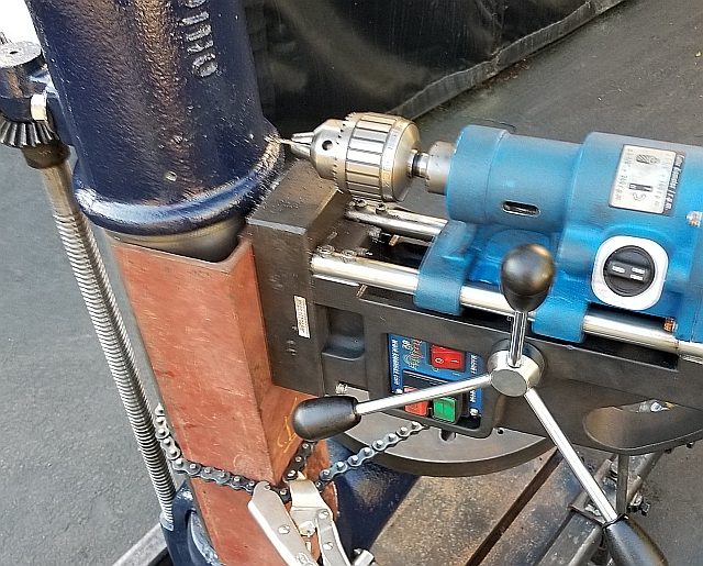
The motor switch installation is clearly visible in the picture on the right at the top of this page..
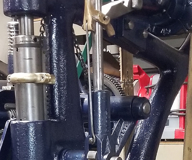
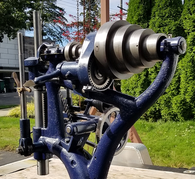
Finally I was ready to move beyond the initial testing phase and really make this machine right and ready to use. The bearings on this machine are nearly all babbitt bearings with split housings. The bearing caps have 4 bolts. I wasn't born knowing how to work on babbitt bearings, and I must have slept through the lesson in school because I really didn't (and don't) know what I'm doing. But the babbitt itself looked fine to me. I redrilled a couple of oil holes to improve lubrication. But the main thing was making shims that go between the halves of the babbitt bearing. When I got this machine all those bolts were finger tight if that. In other words, if they'd been tightened down properly, the shafts wouldn't turn. So it was up to me to make new shims. I didn't do anything particularly brilliant or skillful, just persistently measured gaps and made shims until I had a set that allowed me to get the bearing cap bolts fairly tight without binding on the shaft or allowing any looseness. I learned quite a bit doing this. I still haven't cut the outer profile of the shims on the upper drive shaft, which is why you see what looks sort of like playing cards sticking out in midair. Someday I'll trim them to size.
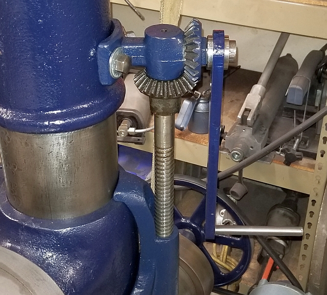
As I've alluded to several times, the drive shaft on top of the drill press is powered by flat belt from the lower drive belt assembly below. It in turn transmits power to the quill via a crown gear (bevel gear). I had read somewhere that you need to set the backlash in that pair of bevel gears by putting a shim under the crown gear. By now I was good enough to realize the thickness I needed. But I was stumped at what to make a .040" circular shim out of. I wanted it to be slippery but not squishy, and for sure nonabrasive. Eventually I found some plastic presentation binders at a store and cut off the covers to make plastic shims out of. I was able to make a fairly clean cut on the OD and punched a hole for the ID and installed it and lo and behold everything seemed fine.
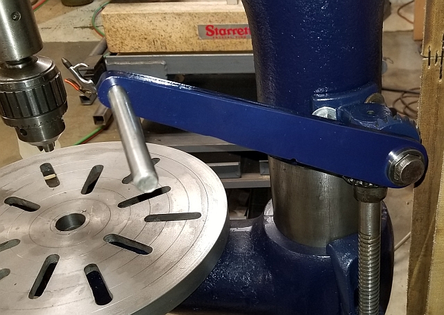
The last item was that this drill press was missing the crank handle that operates the elevation screw. This is important, because this is how you move the table up and down. It needed a 1-1/8" female hex hole, and it needed to be long enough to give enough mechanical advantage so my arm wouldn't get sore cranking it. The table combined with its support casting are quite heavy. Not having any luck finding such a crank handle for sale anywhere, I made one. For the hex hole I bought a cheap used 1-1/8" socket off ebay and parted off the barrel. The socket was made of tool steel but it machined well on my lathe using carbide tooling. The body of the crank handle I torch cut from 3/8" steel plate, using an old pattern cutter I've been slowly working on. It doesn't look laser cut, but it didn't have to. I sanded the worst of it. I machined a hole and pressed the socket in. It was a fairly stout press fit. If I need to later, I can always weld the socket to the handle. But for now I'm going with a press fit. I didn't have any luck wheedling a favor from any of the CNC lathe operators I know, so I just cut a piece of 1/2" round steel and welded it to the other end of the handle. Someday I will make a handle that slips over that and fits my hand better. Anyway, a little paint and it was ready to go to work:
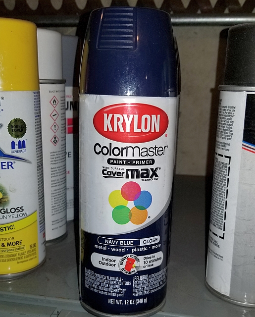
That's about it. I didn't go into detail on such intricacies as aligning sheaves or surface grinding scarred keys. I did all the painting with rattlecans, not being a painter. I liked the paint I used, although some of the reviews I read of it were quite uncomplimentary. Here it is:
Before I finish I wanted to touch on tooling. I have every intention of using this machine; to make it earn its own way as it were. This drill press runs at slow speeds with enormous torque and is best at drilling big holes. To drill big holes you need big drills. I researched the issue and found that drills in the size range 49/64" to 1-1/8" are usually made with a no. 3 Morse taper shank. (Drills 3/4" down or 1-9/64" up come with taper shanks too, just not usually 3MT.) As part of this project I have been collecting 3MT drills. Here is my collection as it stands today:
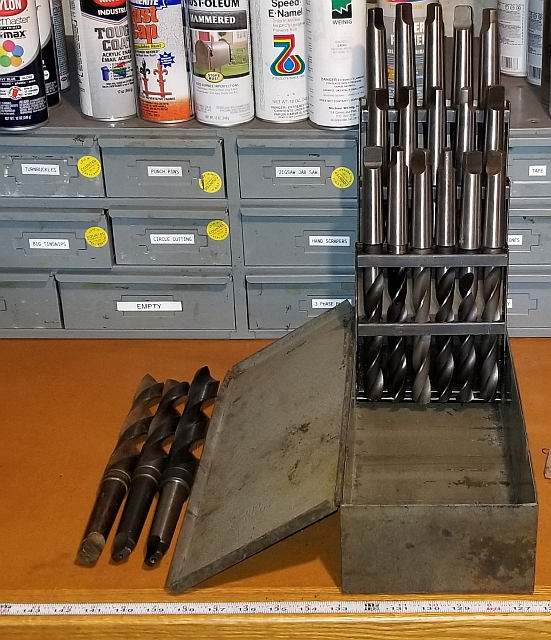
Do you like that Huot drill index for drills from 49/64 to 1"? That was quite a score. I'm still looking for 3 Morse taper shank drills larger than 1". If you know of a good source, please let me know.
In closing, I still plan to make a rolling base for this machine and cobble up a handgrip for the elevating crank handle. I also need to find a permanent place for it in my shop, as well as move around some storage to free up a drawer for the tooling. I have an upcoming project that will require 18 1-1/16" holes through 4 inches of solid steel. That will be a good job for this machine. I had a lot of fun on this project and even if I wind up selling the drill press someday it was a great way to spend some weeks of enforced isolation during the 2020 epidemic.
I'll leave you with a few more pictures. I never get tired of looking at this cool old machine and I hope you don't either!

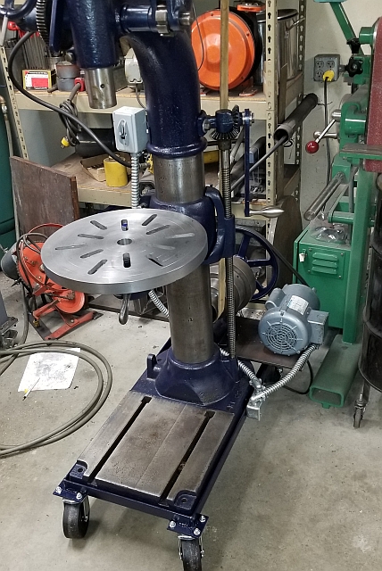
Addendum February 2021: I made a rolling base for the machine. It looks much tidier on a proper base, I think. See what you think:
Thanks for reading!