In my youth I worked for 13 years in Seattle's shipyards. I worked on barges, ferry boats, Navy ships, cargo ships, grain ships, processor ships and fishing boats. I never had any formal training. I went in a completely ignorant laborer and came out a competent shipfitter. I made good wages and learned a trade but more importantly I got to work around a lot of very skilled workers and I absorbed a lot of knowledge just watching them. I learned that it's very possible to move items that are far too heavy for one or a few men to carry, with common sense, a few slings and chainfalls and determination. I learned about cutting, fitting and welding steel and I got to learn a lot about why ships are built the way they are. Along the way I met many characters and accumulated quite a few memories which have turned into stories over the years. I probably should have gone to college along with my high school class and gone on to work at Microsoft and make millions of dollars the way many of them did, but I don't regret those years spent working as a blue collar union tradesman on Seattle's waterfront. Later, I went to college and got a degree in electrical engineering and got to have a high tech career and I made a lot of money. But I always yearned to be making something. I guess I'd caught the metalworking bug early, and have carried it with me my whole life.
I grew up in the muscle car era. I never had a hot car but I had many friends who did, and I did get involved in a fair amount of wrenching. So during my teenage years I started to collect a few tools, nothing more than what I could keep in a single toolbox for wrenches, sockets and screwdrivers and a cardboard box for my jumper cables. In my early 30s, though, I began learning about tools and machines which you could have at home and slowly over the years I have amassed a home shop which I'm proud of. In it I do fabrication and machining and painting and do electrical work and maintenance tasks of many kinds. I have hundreds of friends in a local metalworking club and correspond with many more online via a variety of forums.
One thing that is common to shops of all trades, they all seem to need compressed air. I've owned many compressors in my life. I've replaced belts, motors, motor capacitors and motor starting components like mag switches, but I never had a real solid industrial machine that I'd completely rebuilt myself. I have always had a smallish shop and have learned that vertical air compressors take up less floor space than horizontal ones. So in recent years any compressor destined for my shop had to have a vertical tank. Like most home shops, mine has 240 volt single phase power and, like some shops, mine can make a limited amount of 240 volt three phase power. I never figured my phase converter had the oomph to run an air compressor with a motor larger than 5 horsepower, though.
Let me digress for a moment. One of my other abiding interests has been building meat smokers. In particular, horizontal offset meat smokers made from air tanks from old compressors. So I have learned to keep an eye out for a good deal on an old air tank, since they have a lot of value once turned into cookers. Anyway, in June of 2023, towards the end of the pandemic, I saw an incomplete air compressor project for sale near me.
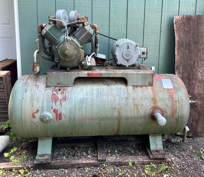
Reading between the lines, I could tell the seller just wanted the machine gone. It had an air pump on it, and a motor, pulleys and belts, but it was not a complete running compressor by a long shot. But the tank was a solid 120 gallon horizontal air tank, and that to me is the ideal size for a meat smoker in someone's yard. So I bought it and brought it home. I paid the princely sum of $100 for it and probably burned $10 worth of gas since it was only one town away. I discovered that the air pump was a Champion R30A and the motor was a solid old 7.5 hp Century motor which had clearly been rebuilt. I soon discovered that the tank was in fact far too old and corroded to have any value as an air tank. I thought about building another smoker, but since I'd just completed another one with a tank almost as large, I just wasn't motivated to take on another big project. So I cut off the saddle (the part the air pump and motor are bolted to) and sold the tank to a guy who was on fire to build a smoker. I sold it for $125 and yes, I told the buyer the tank was past its days as a pressure vessel. This is the original forsale listing image:
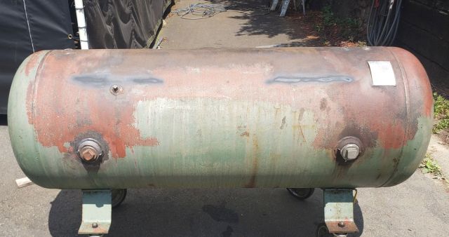
As I mentioned above, this 120 gallon horizontal tank failed pressure testing (which I did with my pressure washer). I sanded the welds where the saddle had been attached, and this is what it looked like when I sold it:
After reading up on the Champion R series air pumps I learned that they have a very robust unloading system built into the pump. This means such a pump should never have to be started under full load. That meant I had a good chance of being able to use it with a 7.5 horsepower 3 phase motor. So I decided to try to rebuild the pump and use it on an air compressor. And this latest project of mine was underway.
A short time later, I spotted another used industrial air compressor. This one had an 80 gallon ASME rated vertical air tank. So I bought the compressor and discarded the air pump. It never had a motor. I pressure tested the tank well above its max rated pressure and saw no leaks, so I figured the tank was still good. Its saddle was too small for the Champion air pump and Century motor, so I cut it off. I welded over the inevitable scars (light welds, not penetrating far, after all this is a pressure vessel) and sanded them smooth.
So, armed with suitable candidates for motor, air pump and tank, I fully committed myself mentally to turn this pile of parts into a rebuilt industrial grade compressor.
At this point, I want to go over what I have learned about various aspects of reciprocating air compressor pumps (pumps with pistons). They aren't all made the same way. In several areas the manufacturer has a choice of two solutions and invariably one is more reliable but costs more. The first of these is valves: there are disc valves and there are reed valves. They both work, but reed valves break sometimes and thus need more maintenance. The next is lubrication, which is implemented either with a pressurized system driven by an oil pump (often with an oil filter) or by arms that stick out of the crankshaft that splash oil around enough to lubricate the crank, the rods and the pistons. Obviously, pressure lubrication is more expensive. But it's also more reliable. If you let the oil get too low splash lubrication will just stop working. Splash lubrication works fine as long as you keep oil in the crankshaft. A 3rd differentiator is the method of unloading. Better pumps have solid mechanical unloaders integral to the pump, whereas cheaper air pumps rely on the compressor's pressure switch to allow for easier starting. Finally, better quality pumps have replaceable connecting rod bearings whereas the cheaper pumps do not. It is clear that when the connecting rods wear in the cheaper pumps, a rebuild would require new rods, which are likely to be expensive enough to make the rebuild impractical. So the pumps with (affordably) replaceable rod bearings are considered to be likely to have a longer service life.
So, to summarize:
CHEAP				EXPENSIVE
reed valves			disc valves
splash lubricated			pressure lubricated
pressure switch unloader		mechanical unloader
rod bearings not replaceable	has rod bearing inserts
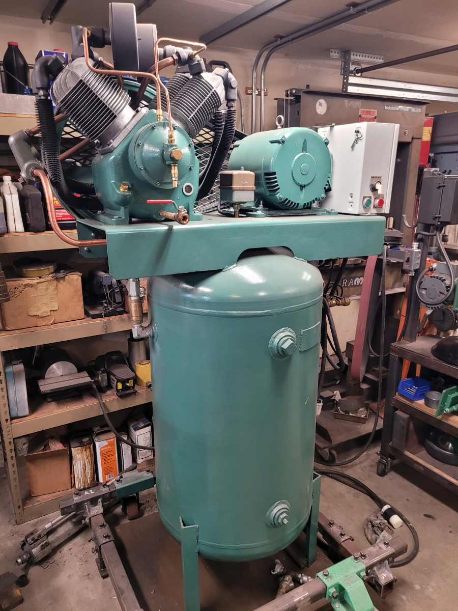
An example of a machine built to the highest standard is the Quincy QR series. A new compressor with a QR pump costs nearly as much as a new car, though. The pump this article describes is from the Champion R series, which has disc valves, is splash lubricated, has a mechanical unloader and does not have connecting rod bearing inserts. (In its defense, the pump was built in the 1970s and I did not detect any wear at all where the aluminum connecting rods bolt onto the crankshaft.) Note: Champion has another series of air pumps, the RV series. These have reed valves, are splash lubricated, have mechanical unloaders, and no bearing inserts. In other words, they have different (cheaper) valves. The pump discussed in this article is a Champion R30A and the air pump off of my 5hp single phase Champion is type RV15A.
Back to my story. When I tore down the R30A air pump, I found two issues: many of the valves were completely clogged up with corrosion and filth, and several of the piston rings were stuck in their grooves so they were no longer pressing outwards against the cylinders. And, of course, there was carbon on the pistons. So, a valve and ring job was in order. Now I'm going to describe the rebuild process in some detail.
I started by removing the air pump from the tank. It weighs close to 300 pounds with the flywheel pulley installed, full of oil. I used a car mechanic's technique of removing 2 bolts and bolting them back down with a light chain between them. A portable shop crane with a single hook (like an engine hoist on steroids) can then lift the air pump easily. I put the air pump on a hydraulic lift cart so I could easily work on it.
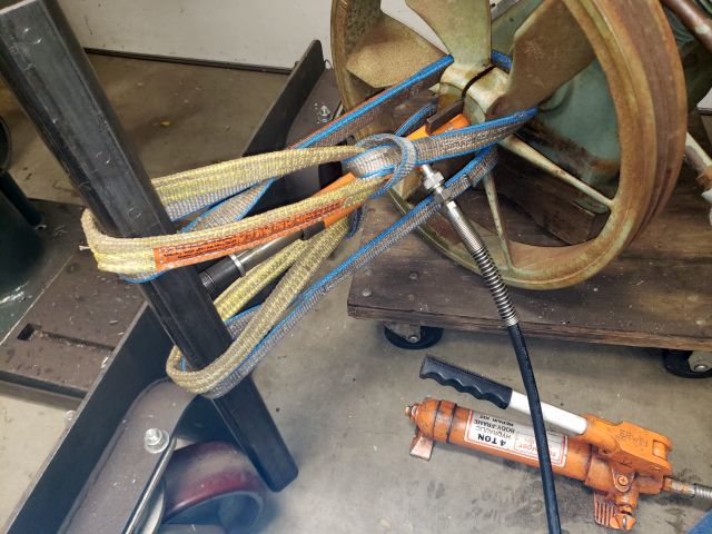
I removed the big pulley, which Champion calls a flywheel. It was challenging to remove. I did not have the right puller. I started by completely removing the pinch bolt and driving a steel wedge in the crack. In the end I cobbled up a puller of sorts using a hydraulic pump against the end of the crankshaft, with its ram bearing against a strong piece of square steel tube fastened to spokes of the flywheel. I was able to pull the flywheel off by just jacking the pump. Not elegant, but it worked. I think driving the wedge in the crack really helped. In the next photo you can see the wedge in the crack if you look hard enough.
I removed the two intake air cleaners. I don't know if they were factory, but these were made by Solberg and had replaceable elements. So I ordered new air filter elements. I derusted the filter canisters and primed them with Rustoleum automotive gray primer.
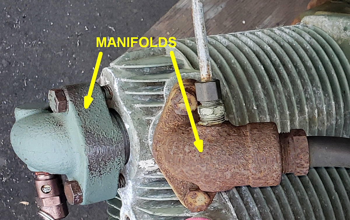
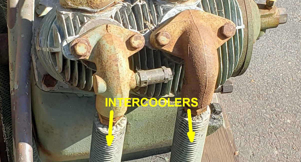
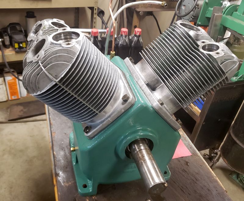
Next I removed the intercoolers. An R30A pump has two intercooler tubes. The easiest way I found to remove those was to unbolt the valve manifolds attached to the intercooler tubes and remove the tubes with the manifolds still attached. On the bench, it was much easier to bring enough force to bear on a compression fitting so that I could remove it from the valve manifold. The use of the word 'manifold' confused me when I first encountered it in Champion literature. Here is a photo of the as-received pump with the manifolds called out, so you can understand what I mean.
This shot shows the intercooler tubes where they are attached to their respective manifolds.
With the intercoolers removed, an inspection revealed a lot of cooling fin damage. The intercooler was made of heavy copper tube 3/4" OD with aluminum spiral wound and crimped around it. It is possible to buy new intercooler tubing but I have no idea how to bend such tubing with aluminum fins wound around it. So I never considered replacing the intercoolers. I searched the web for techniques of straightening bent intercooler fins, but I didn't find much. So I took two really small straight screwdrivers and a pair of tweezers and patiently straightened each bent fin. I think that fin material must have been pure aluminum because it was very ductile. That took awhile. The fins were jagged on the outside from damage in several areas. This looked bad, but looked much better after the fins were straightened and sprayed with a good coat of primer. It didn't wind up costing me anything to repair the fins on my intercooler tubes and just that one fix made the whole air pump look way better.
After removing the intercoolers, I removed the aftercooler tubes, which you could also call the discharge tubes. There are two, again 3/4" OD copper tubes with compression fittings at both ends. Unlike the intercoolers, the aftercoolers are not wound with aluminum fins for heat removal. These tubes join a couple of feet away at a cast aluminum manifold. The tubes and manifold had been painted, but I removed the paint and polished the tubes. I believe that will improve heat transfer through the tubes, allowing the aftercoolers to do a better job of cooling the compressed air. The next shot shows the aftercooler pipes still attached to the aluminum manifold, as well as the valve manifolds and valves, all clean and layed out on a board.
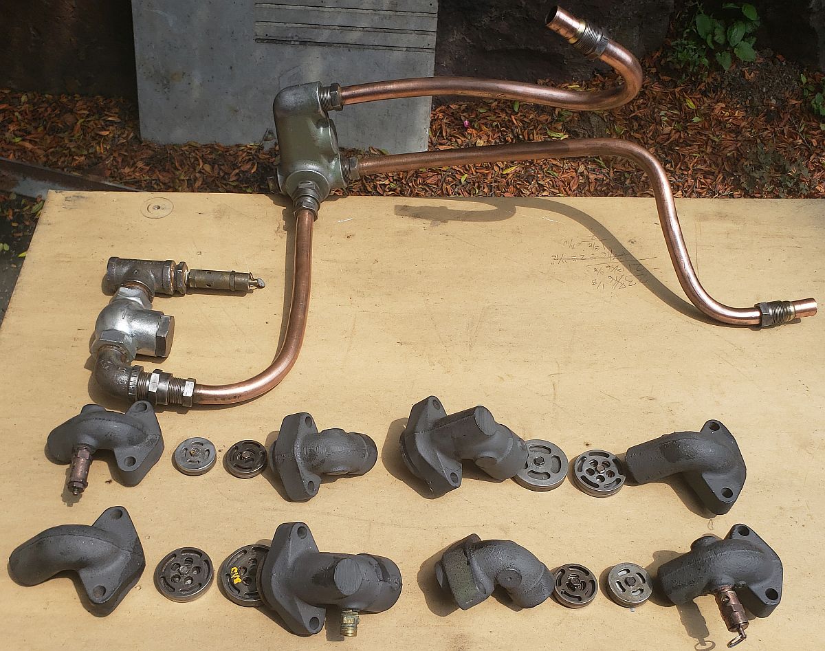
With the intercooler and aftercooler tubes removed, the next step was to remove each valve manifold and its associated valve assembly with its top and bottom crush washers. I cleaned, derusted and primed the manifolds, after making very sure I knew where each one went. The valves are disc valves. Each one was a hardened disc inside a little cage with a spring. The assembly came apart with one screw (loctited), and then everything could be cleaned and lapped. I lapped the discs on a piece of plate glass using wet-dry sandpaper taped down. I derusted the rest of the parts with Evaporust. One of the first 7 valves had a disc that was too corroded to lap flat again. I ordered a new one. I was able to restore those first seven valves. The 8th valve was too far gone, so I bought a new valve assembly. Champion valves are held in place fastened to the air cylinders with manifolds. There are crush rings on top and below the valve. I bought a set of those crush rings for less than $40.
After going through the valves, I drained the old oil into a container so I could measure the volume. I knew I was going into the crankcase so the oil had to come out regardless. I didn't like the drain setup so I replaced it with longer pipe made from brass.
A word on compressor oil: you can spend a lot or a little on oil. The guys who make lubricating oil say you should buy new oil and replace the old oil every few months, and be sure to buy their latest (and most expensive) synthetic oil. If you listen to Champion, well, I have the R30A manual from the 1970s and it says to never use synthetic oil in any Champion pump. I also have the latest, current manual, and it says to only use synthetic Champlube. My guess is that in between Champion got into the compressor oil business. Anyway, I ordered 4 quarts of Chicago Pneumatic 30 weight nondetergent compressor oil from Zoro for about $10/quart. After I run this compressor for a few months I will probably change the oil. At that time I might switch to synthetic but if I do I certainly won't change it more often than once a year.
With the oil drained, I next unbolted the two cylinders (jugs) from the crankcase and pulled them straight up and off. It was immediately apparent that new gaskets were going to be needed, so I ordered a set. I set the cylinders aside and addressed the pistons and rings next. The tops of the pistons were coated in carbon, and several of the piston rings were stuck in their grooves so they did not press outwards against the cylinder walls as they are designed to.
The first thing I did was to remove the wrist pins. These were held in with internal circlips which were quite recessed. None of my circlip pliers were going to work. I wound up buying new circlip pliers at NAPA, and these worked. So I got the pistons loose from the connecting rods. I'm sure I chucked the pistons, wrist pins and circlips all into my ultrasonic cleaner. Then I decided to clean the pistons.
I don't remember how I got the carbon off the pistons. Probably I used a fine bristled wire cup wheel on an angle grinder after the pistons had gone through a session in my ultrasonic cleaner. Anyway, I was able to get the tops of the pistons cleaned up and serviceable. I was able to get all the piston rings off intact. I lapped them a bit and then inspected them. They looked fine to me, so I reinstalled them, again without breaking any. I didn't have any special ring tools, either. I just used basic hand tools and my fingers. After cleaning and reassembly the rings were no longer bound in their grooves and the ring and valve job was completed.
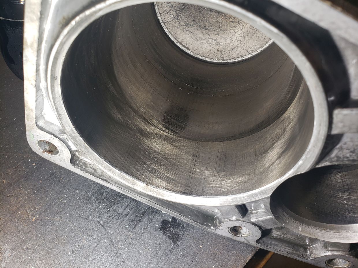
Next I moved on to cleaning the cylinders. Champion cylinders are one-piece type i.e. there is no removable cylinder head. My cylinders had a lot of fins with narrow spaces between them, and unfortunately those spaces had been collecting oily dirt and grime since the 1970s. In other words, they were really dirty. In such cases I have learned to start by vacuuming the loose leaf mold and insect nests, followed by spraying on degreaser, letting it sit, and then pressure washing. This got a lot of the dirt off. I'm sure I did what I could with rotary brushes and the like, but that avenue of cleaning was clearly insufficient. In the end I prevailed on my buddy with a bead blaster so I was able to clean the cylinders completely that way. They had been painted, but the bead blasting removed what paint was left after earlier cleaning steps. I decided that rather than paint the cylinders again, I'd leave them clean and uncoated as they came from bead blasting. I like that look and it can only help with cooling. I cleaned the cylinders and was gratified to see the original honing marks still visible:
I also removed the connecting rods from the crankshaft and disassembled the bottom end completely and cleaned everything. I was happy to see that the inside of the crankcase wasn't too dirty and had no rust at all. The real reason I knew I had to completely tear down the bottom end to the point of removing the crankshaft was that I knew the crankshaft's main oil seal leaked oil and needed replacing. Also, the oil sight glass had been leaking for many years and it needed replacing as well.
The unloader mechanism is called the governor assembly by Champion. The governor case and associated parts were all in excellent condition with no rust or binding anywhere. The main crank bearings looked new. They are large roller bearings and I didn't see any reason to replace them. As I mentioned above, I did replace the rear seal on the crankshaft. I had learned from experience that the seal on the flywheel pulley side of the crankshaft often leaks and should be replaced. The compressor parts sites wanted something like $40 for a new seal but I found one on ebay for $8 shipped, also new. It pays to clean the old oil seal and read the numbers! The new seal was an easy tap in over the end of the crankshaft as long as the large flywheel pulley is off. The sight gauge was easy to tap out from the inside of the clean crankcase, and the new one pressed right in from the outside. After reassembly there were no more oil leaks at all.
After cleaning the bottom end of the air pump completely, I reassembled the crankcase and masked it for paint. As for the paint itself, here's the story. I have another Champion vertical compressor, a 5hp vertical, which this compressor is destined to sit next to. So I thought it would be worth it to buy actual Champion green paint so the two compressors would match. Champion does not sell their paint. But I found that I could order it by the quart (no, they don't sell it in spray cans) from this vendor:
Riley Paint Co. (no web site or online ordering as of 2023)
Burlington, Iowa 319-753-1667 / 800-635-2663
The paint is Riley Paint's LP3386 Champion Green.
It wasn't cheap, either. I think a quart was about $35 and they charged me about another $40 for shipping and handling. At the time I remember thinking what if one quart wasn't enough? Well, I was able to stretch one quart to make it work but two quarts would have allowed me to do a better job.
After masking I painted the crankcase with 2 coats, brushed on with a good quality brush. I'm a rattle can guy and did not want to monkey with HVLP when I had such a limited supply of paint, so I just brush painted everything. After removing the masking, the bottom end of this air pump looked enormously better.
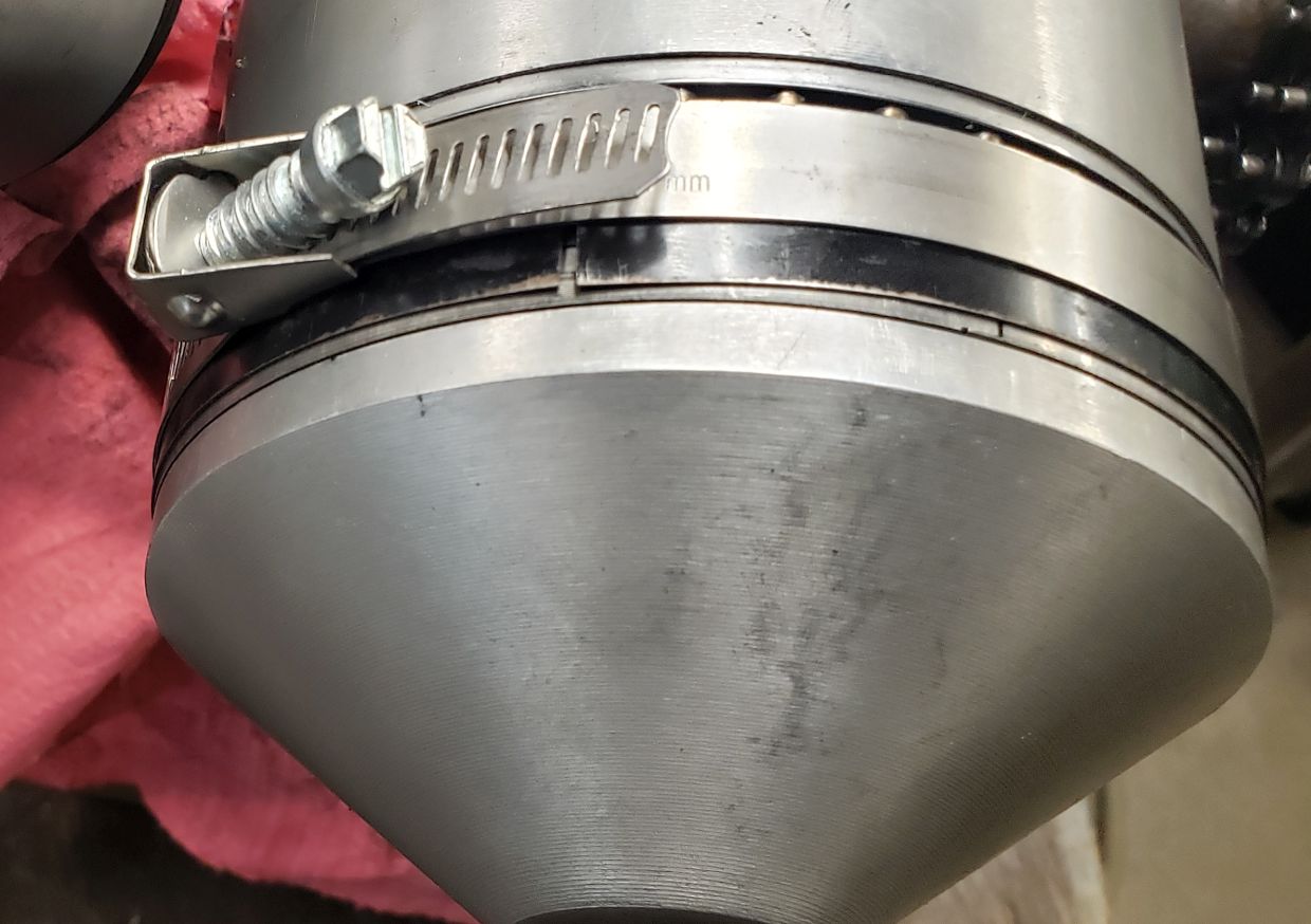
Next, I installed the connecting rods. Then I got stymied installing the cylinders for the lack of the right ring compressor tool. In the end I made one from a big radiator hose clamp and a piece of steel strapping scrounged from a pallet board. I remember setting the piston on the table of my arbor press with the cylinder resting directly on the piston and a hardwood board above the piston. I was able to apply some pressure to the board while tapping on the top piston ring with a small hammer and screwdriver, and eventually the cylinder dropped down over the ring. Once the top ring was in, pressing the cylinder down slid my ersatz ring compressor down and the remaining rings went right in. Then I placed the cylinder gaskets down on the crankcase, because I knew they were super easy to forget. Here is an ersatz ring compressor that worked for me:
Next I pushed the pistons out enough so I could slide in the wrist pins and fish the circlips into place, thus installing the assembly to the connecting rods. Afterwards, the cylinders slid fully down into place (with the gaskets carefully aligned), and I was able to get them bolted and torqued down.
It took just five or ten minutes to write this paragraph but it took me nearly a week to get through this step in my shop! Here is what the air pump looked like after I got the cylinders back on:
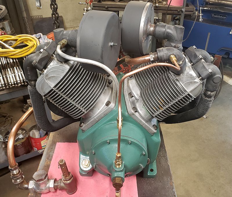
After the cylinders went back on then I installed the valves, manifolds, air filters and intercooler tubes. This was straightforward wrenching. The air pump came to me with two painted aluminum tubes running from the governor case up to the discharge valve manifolds. I didn't care for the look so I remade those tubes using copper tubing which I polished and left bare. It took a couple of tries to get the bends just right, but in the end I think they look much better. In the next image I have replaced one of the aluminum tubes but the other is still there. You can compare for yourself to see how you like copper vs. aluminum.
Once the discharge tubing was installed, I set the air pump aside and started working back on the tank again. Recall that I had cut off the saddle, or top plate, from the 120 gallon horizontal tank that eventually got sold to the smoker builder. My plan was to reuse that old saddle plate on the new vertical tank. I had to do a bit of work on the old saddle first. Like all such saddles, the sides have cutouts in them. The side openings in the old saddle were too big - they didn't even touch the new tank. So I cut out some skirts and fit them in the side openings and welded them in then sanded the welds smooth. I had cut new side openings in the skirts which were the correct length for the vertical tank. With the sides fixed, I had to cut a clean central hole, as the vertical tank's top end had a 3/8NPT hole in its end for the pressure switch, and the old saddle had no hole in it so I couldn't plumb in a pressure switch. I wound up cutting a 3" hole with a hole saw on a hand drill. It wasn't fun, or pretty, but I got the hole in pretty much in the right place and the little imperfections don't really show, so it was all good. Now the wide old saddle was ready to be installed on the tank. But the tank top wasn't ready yet. Under where the old saddle had sat was a thick layer of oily dirt, along with a little rust. I had to work on that quite a bit to get it clean but eventually it all came off and it was time to put the old saddle on the new tank.
To do that job, I carefully leveled the tank so its sides showed vertical with a two foot construction level. Then I placed the saddle onto the tank and leveled it carefully, which aligned the saddle to the tank. Then I scribed the bottom of the saddle where it touched the tank. Then I took the saddle down and cut the scribe lines and sanded them smooth and put the saddle back up and realigned it, then welded it in place. I made an embarrassing mistake here. I welded the saddle on backwards! The front of the air pump would have faced the back of the tank! I could have made that work somehow but I would never have been happy about it so I reluctantly cut the welds with a zip disk (keeping the cutoff wheel away from the tank itself) then sanded things smooth, turned it around the right way and rewelded it up. Now it's nicely aligned and solid. If I hadn't read my notes I would have never even remembered that mistake. All's well that ends well.
With some rainy weather approaching, I put the tank with its new saddle inside and began working on the motor. I mentioned above that it had been rebuilt. What I meant was that its end caps had been removed to replace the bearings. Prior to removal, a former owner had punched in witness marks so he could put the end caps back on exactly as they came off. I do this too when I disassemble a motor, so I recognized his marks. When I spun up the motor it sounded smooth and quiet, no extraneous bearing noise at all. The quality of the installed bearings plus the witness marks told me the motor had been rebuilt. So all I really had to do was to paint it with some of my Champion green paint.
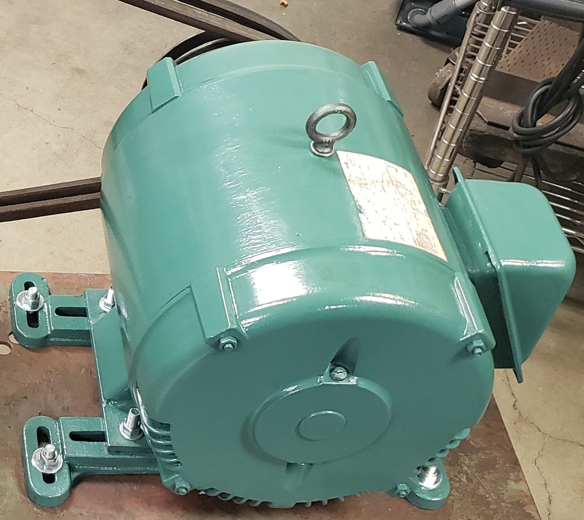
There isn't much interesting to tell about painting an electric motor. I will say that I removed the junction box and did a fair amount of wire brushing to prep for paint. I removed the motor's junction box because I wanted it to face the other way and also because it had sat outside for a long time and had rusted a bit so I needed to derust it before painting. Anyway, I painted the motor and junction box, again with a brush, and put them back together. Good to go.
I have a gantry crane in my shop driveway. I can lift its hook up to about 13 feet above ground. I cobbled up an eyehook arrangement that screwed into the pressure switch port on top center of the tank, and lifted the tank way up in the air. I removed all of the drain hardware from the bottom, knowing it would be replaced later with tubing to an automatic condensate drain. I used a pneumatic needle scaler (needle gun) and also an angle grinder with coarse twisted wire cup to remove paint from the tank all the way up including the saddle. Then I painted the tank, lifting it as needed. I started with reddish brown primer, then stretched the dwindling quart of green paint. I got one full coat plus part of another on. Maybe someday I'll get donated another quart of Champion Green so I can get the rest of the tank's second coat on.
After a few days in the sun the paint was sufficiently cured enough to that I could work on it without destroying the new coat of paint, so I installed the air pump and motor with the central eyebolt still installed. I connected that eyebolt to my shop crane and started to lift the compressor, planning to roll it around upright while lifted by my shop crane. What I discovered was something I should have thought about much earlier, which was that with a much wider saddle on top and a much heavier air pump way out towards one end of that saddle, even with the motor on the other end acting as a partial counterweight the whole thing was extremely tippy, unstable and in fact dangerous. Needless to say this didn't make my day. With rain approaching, I shelved worrying about a long term solution and removed the air pump and motor and moved them on my trusty hydraulic lift cart and moved the (now balanced and stable) tank with my shop crane. I rolled the whole shebang under cover and started working on a belt guard.
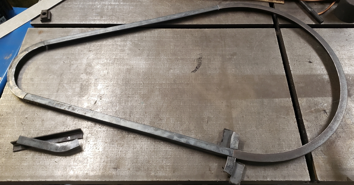
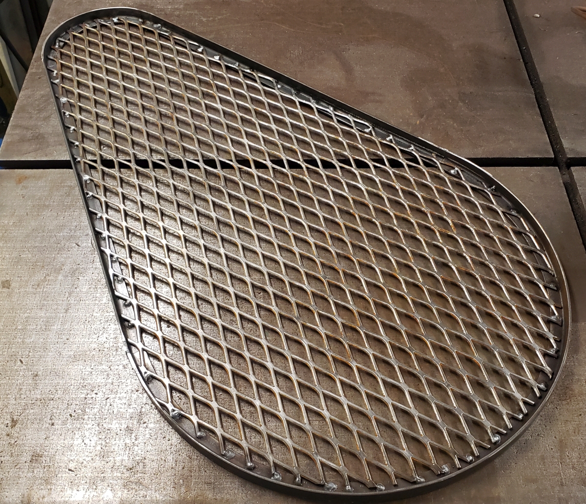
I've done a fair amount of steel fabrication plus I'd had a lot of time to decide how I wanted to go about making a belt guard. Without going into too much detail, I decided to make a side frame from 1x1x1/8" angle iron, then use 3/4-9 expanded steel for "fabric" to fill in. The tricky part was bending the angle iron toe-in into circular arcs of the right radius. Anyway, I made a drawing and determined I needed the big end to have a 20.5" radius, the small end to have a 7.75" radius, with a center-center distance of 21.5". Some shop math gave me the requisite angles and it was time to get out the Hossfeld bender. I have the toe-in die set so setup was simple. I used the 12" radius die and didn't pull each bend fully. I got very close to my target 21.5" diameter first go. I actually formed the smaller circular arc by hand around a round thing from my shop floor. After playing a little with springback, I had my arcs bent. I did a little layout work and then cut the ends to the right angular dimension and then cut two straight lengths of my light angle stock. These 4 pieces then were welded into a continuous outline.
Then I drew around the frame onto my expanded steel and cut it roughly out with a plasma cutter. Then I carefully drew my shape onto the expanded steel with yellow layout ink and used a Whitney hand shear to trim the expando to the correct size. I lay the expanded steel into the side frame and used a MIG welder with 0.030" wire to make a series of small MIG welds to secure the expanded metal in place. I was gratified how professional it looked.
Then I cut some rectangles of 1/8" plate, and repeated my bending process to make the pieces to join my two sides together. I welded everything with MIG welds and sanded them smooth. There was a bit of distortion but nothing that would show, so I called it good. I bent up some strap and punched holes to attach the belt guard in place, then painted it. Beauty is in the eye of the beholder, but I personally think it looks terrific!
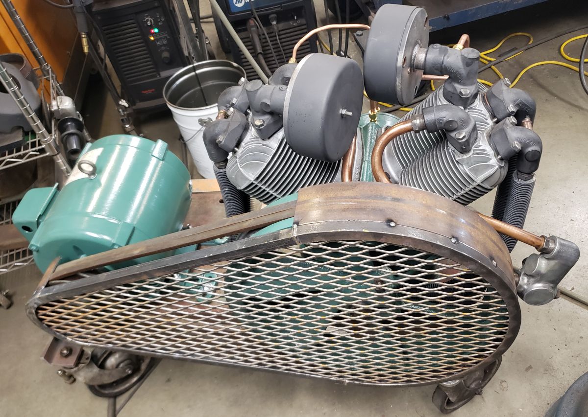
In this picture the belt guard isn't quite finished, and it's just sitting over the wheels. But it gives you a good idea how it went together.
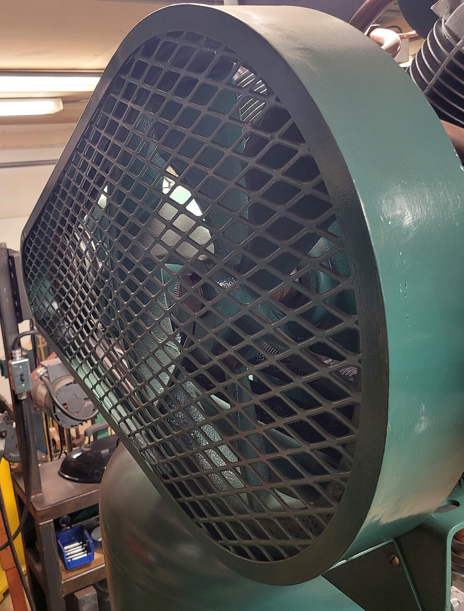
Here is a photo of the finished painted installed belt guard. After it was finished and bolted on solidly it seemed very strong and rigid. I probably overbuilt it but if I had to do it over again I'd do it exactly this way again.
Under my outside canopy and out of the weather, I used my shop crane one more time to lift the air pump and then the motor into place and get them aligned and bolted down. I still had the problem of how to connect the discharge tube manifold to the main tank, but I left that for a bit and installed the belt guard. Then I moved on to making the discharge tube. Here I learned another valuable lesson: the 3/4" copper tubing they sell at the hardware store is more accurately called copper pipe, and pipe is sized by the ID. Although I'd looked at 3/4" copper pipe for years I'd never noticed, but it's OD is 7/8" and all my fittings need tubing with 3/4" OD. Furthermore, the tube which came off from before had walls a full 1/16" thick, and the copper pipe at the box stores wasn't even half that thick. It turned out heavy copper tubing is used in the HVAC industry. In the end I convinced a HVAC installer to give me a bit of HVAC 3/4" OD copper tubing with heavy wall, just over 5/8" ID. I cut it to length by eye and then scratched my head for a day or so while I sussed out how I was going to go about making the bends I would have to make to put it into place. I did have some leeway in that there was some hardware needed between the discharge tube and the tank wall. I needed a check valve and a pressure relief valve. And I could route those fittings any way I wanted to make the bends simpler. To minimize the fitting count I sprung for a pair of stainless hydraulic pipe fittings from Surplus Center. I had a nice NOS/NIB inline check valve in my plumbing parts bin, so I used that.
Incidentally, I learned something about plumbing. The right way to assemble pipe so that it doesn't leak is to use pipe dope, then thread a fitting in as far as it would go by hand and then turn it 2 more complete turns with a wrench. I used non-drying Gasoila for pipe dope because I've had really good luck with it on other projects.
Working with the heavy copper tube was another skill I had to figure out as I went along. The tube is annealed and comes in a coil. I cut off a piece and straightened it before attempting to bend it. I had a lot of trouble straightening it because even annealed it was very stiff. In the end I just pushed the bends out pressing the tube between hardwood boards set up in a big arbor press. After that the tube wasn't round any more and the ends wouldn't fit into the compression fittings. I turned a short piece of round bar in the lathe just a few thousandths of an inch smaller than the ideal tube ID. I rounded the front to a rough approximation of a dome and then polished that in the lathe. With some oil, I was able to push that "mandrel" through the tube which rerounded it reasonably well. I used a tapered pin which started its life as a jeweler's ring sizer to further round the ends until they once again slipped right into the compression fittings. After all that, I had a nice straight piece of 3/4" OD copper tube to work with.
I borrowed a Parker tubing bender from an old friend, and lo and behold on my first try I bent up a usable discharge tube with just a little extra to trim off on the ends. The bends are smooth and true but do have slight wrinkling on the insides. Given that I had no alternative way to bend the tube, plus the fact it was a major PITA to straighten a new piece to work on, I happily installed the new discharge tube in place and decided to live with the wrinkles. Then I moved back to the problem of how to move the compressor, which sat on only 3 legs and is quite close to tipping over even just sitting still.
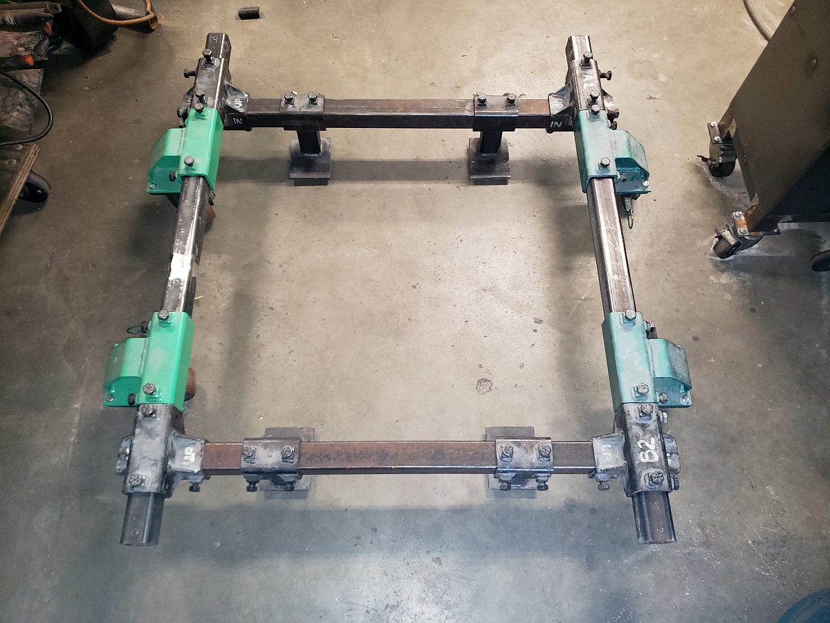
I picked up some drops of 3/4" plywood and cut two 30x30" squares and glued them together to make one piece 1-1/2" thick. I made a spreader bar arrangement for my shop crane and rigged it up so I could lift the heavy end of the saddle just enough so I could slip the board under the compressor's foot. That worked fine. In fact, while it was up in the air I was able to wrestle the second foot onto the board as well. I lowered the tank so the heavy end 2 feet sat solidly on the board, but left it rigged so if it did tip the crane would catch it. Around the other end of the saddle, I again got out my 4 ton portapower. I used a bunch of its attachments to extend the cylinder almost as long as the distance between the ground and the saddle. Then I held it vertically under the light end of the saddle and pumped the handle and very slowly and controllably lifted up the free end of the saddle until I could slide a 2x6 under the 3rd leg. That 2x6 piece was butted up against my board and was a good height match. Then I unweighted the heavy end again by lifting up my shop crane a little, and simply skidded the air compressor onto the board. A little more maneuvering and it was in a good position, so I lagged down the 3 feet to the board. With the base of the tank a 30x30" square, the tank was now much more stable and I was able to use a shopmade machinery moving dolly to roll it into the shop. Here is a shot of that dolly:
And here is a picture of the compressor lagged to its board mounted on the machinery moving dolly, back in my shop.
I had started this project back in June, and didn't get the thing rolled into my shop until early November. Needless to say, late fall and winter weather in Seattle involves plenty of rainfall and I sure wanted the machine inside before that happened. That goal achieved, I moved on to the electrical controls.
Naturally, I had been thinking about how I wanted to control the compressor as well as how to house the control components. From my friend with the endless electrical junkbox I got a size 1 magnetic starter with 120 volt coil, start and stop switches, a 2:1 control transformer, and a 3 position switch with the positions labeled HAND OFF AUTO. The HOA switch's "faceplate" (the part with the lettering on it) was only partly legible so I ordered one from Amazon along with a DPST relay and a 6x10x12" electrical enclosure and those were the only parts I had to buy. I wanted a control system where if the power went off and then came back on, the air compressor wouldn't start again until I reset it. The Brits call this a "no volts release" which I like so I'm going to steal it. My plan was to bring 3 phase power into my cabinet from the wall, labeled L1 L2 L3, L1 and L2 being supplied by the power company and L3 being supplied by my phase converter. My control system would derive 120 volt power from L1 and L2 with the control transformer. A start/stop switch driving the relay's coil would provide the no-volts release, and after that the HOA switch would allow me to turn the machine on to run for a short time (HAND) or to turn it completely off (OFF) or to let the pressure switch control it normally (AUTO). After consulting with some helpful guys online, I came up with a schematic diagram.
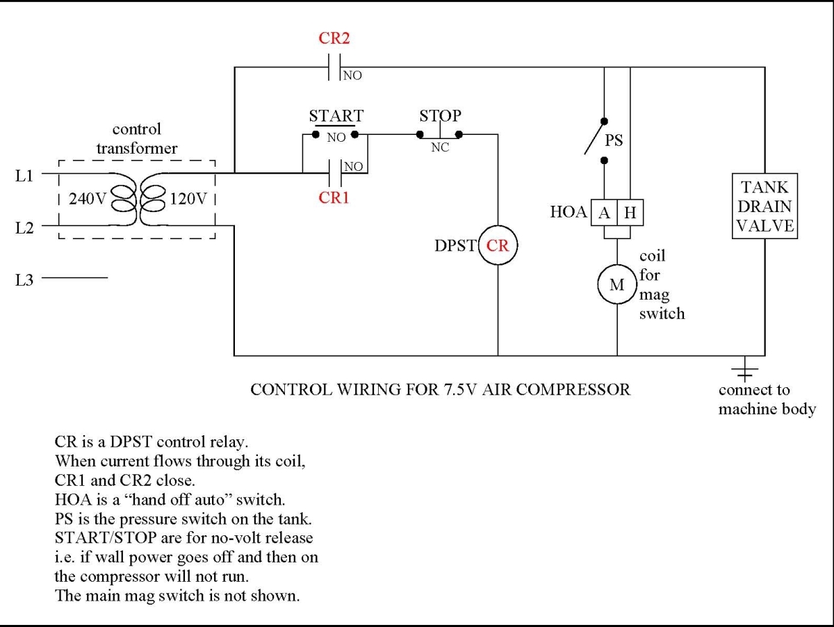
It is important to understand that the control relay CR switches both CR1 and CR2. As long as the START button has been pushed, control passes to the HOA switch. When the HOA switch is set to Auto (A) then control passes to the pressure switch (PS). This is the normal mode of operation. If I am doing some testing or just want to hear it run, I can bypass the pressure switch by setting the HOA switch to Hand (H). In this case the compressor will run without any control until the operator takes the HOA switch out of Hand mode. Now, if the wall power goes off, the control relay opens its switches CR1 and CR2 and the compressor will stay off even when the power comes back on, until the Start button is pressed again.
What came next was mounting the electrical box to the saddle, installing the components in the electrical box, and wiring it up. After scratching my head for an embarrassingly long time, I decided to screw a piece of flat bar to the bottom of the electrical cabinet. The flat bar is wider than the box and has holes punched in the ends where it bolts down to the saddle solidly. The screws are flathead screws that are countersunk into the bottom of the flat bar so that the bar sits cleanly on the saddle. The bar provides one axis of support for the box. If that were the only one, the box would flex and bounce around most unsatisfyingly. So I added another flat bar that goes from the top of the box across to the top of the motor, where it attaches to the central lifting hole. The electrical enclosure box hangs out over the end of the saddle, so cables can hang straight down from the bottom of the box.
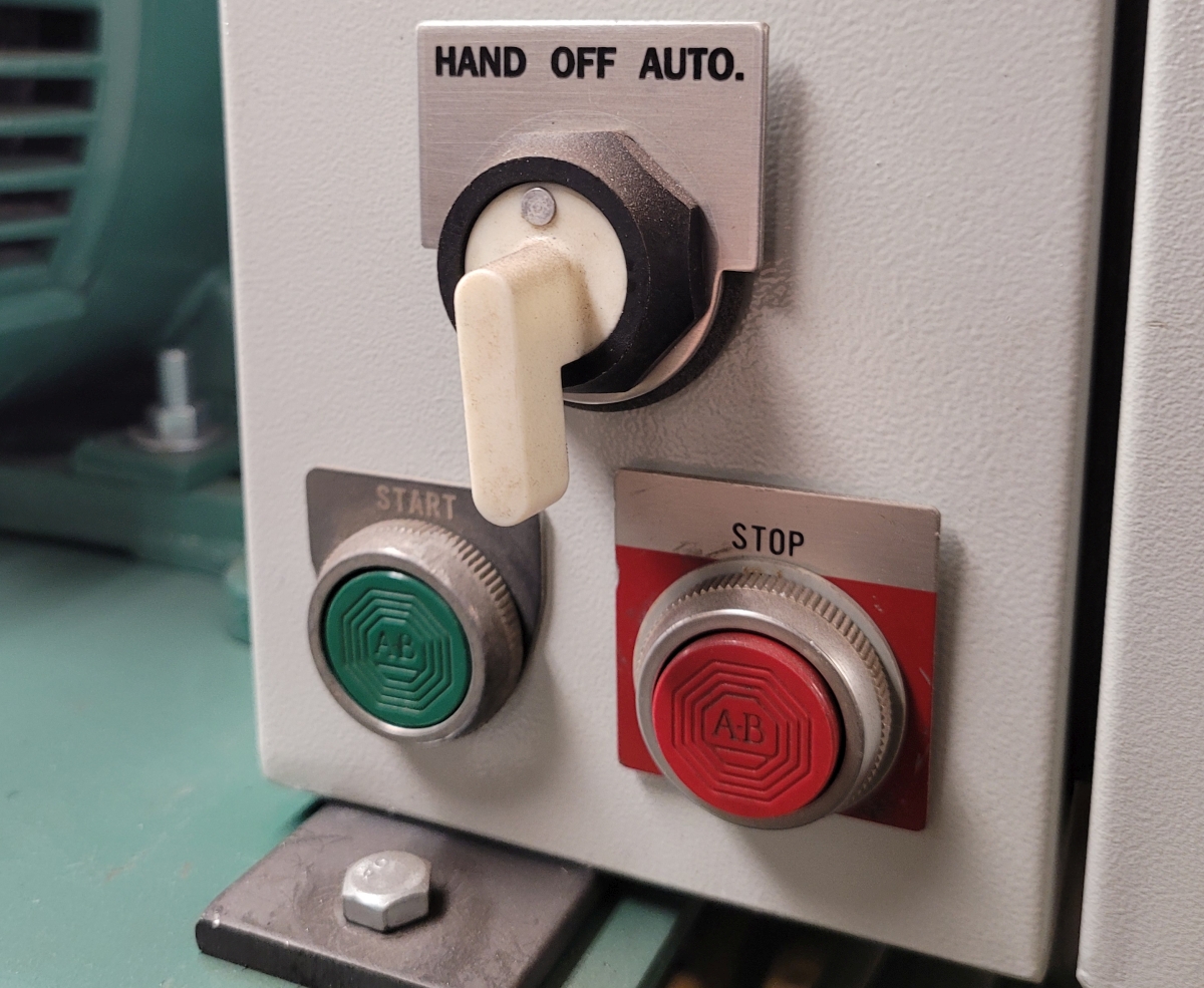
This is what the operator sees. It is on the front of the machine. To me it looks nice and clean. Note that nobody told me I had to implement a no-volts release control system for an air compressor. I just didn't like the compressor roaring to life when the power came back on. It seemed vaguely unsafe. Since I was designing the circuit, I got to pick how it worked.
I used an old Square D pressure switch. Its top cover was cracked but I was able to glue it with cyanoacrylate glue and the glue joint appeared mechanically sound and was all but invisible, so I used it. I just needed to use the pressure switch in off/on mode, so I took an old power tool power cord and connected the black and white wires to the HAND switch and 120 volts, and connected the green wire to ground. At the other end, I wired the black and white wires to two of the terminals and wired the green wire to ground. I ran that cable into my control cabinet via an inexpensive cable gland strain relief. I routed the cord under the saddle then up the side of the pressure switch where it went in to the pressure switch body via another cable gland. This made for a clean installation, as the cable is not particularly visible from the front side of the compressor.
After wiring the control circuitry in the electrical enclosure I can say I wish I'd made it easier to connect multiple wires to the output terminals of the control transformer, as the 120 volt power the transformer generates is routed to quite a few places. I got it done but little terminal blocks would have made it go a lot easier.
With the electrical bit done, I moved on to the auto drain. I purchased a couple of good quality auto drain units a few years ago off ebay, planning to use them in an air piping system I never built. I decided to put one of them on my new 7.5hp compressor and the other on my previous 5hp compressor.
I cut the plug off of one of them and ran the cable into my compressor's control cabinet via a cable gland strain relief. Inside, I wired the cable to 120 volts. This kept me from having to run the power cable to the wall.
The vertical tank's "feet" were nothing more than three pieces of 2" angle iron welded more or less vertically around the tank. To hold the auto drain unit, I first cut and bent a piece of flat bar which bolted at each end to a vertical leg. In the middle of that bar I welded a little 3x6" plate with holes drilled in it to mount the auto drain unit. This simple arrangement held the auto drain unit up off the floor. I used brass pipe fittings and 3/8" copper tube to plumb the tank's lower central drain hole to the auto condensate drain. I routed the copper tube by bending it around a pulley, forming a single loop with two short straight ends. I was able to open this loop into a helical bend, and trim the ends to fit the 3/8" compression fittings at each end. The mounting bracket and plumbing connections seem strong and reliable. My experience with compression fittings on copper pressurized air tubing is that you might get air leaks at first but once you get those stopped they won't come back.
To keep things simple I decided to just plumb a 1/4 turn ball valve to the tank's discharge port. The tank's side is threaded 1" NPT so I used a bushing to 1/2" NPT and then a 1/2" NPT run tee (male-female-female). The tee was oriented with one leg straight up and the other straight out. I put a 200 psi gauge in the vertical leg of the tee and a ball valve in the horizontal.
After all the setbacks on this project, I had high hopes when it finally came time to pressure test everything. The compressor started up fine initially but when I tried to restart it with some pressure in the tank the motor pulley turned slowly for several seconds until finally the output breaker on my rotary phase converter tripped. This was discouraging because I had figured since the Champion pump has such a robust unloader system, that it would always start as if there were nothing in the tank.
I turned on two other 3 phase machines in my shop and then tried again, and with the extra boost from those two machines the compressor spun up normally. It doesn't appear to be a problem with the air compressor, just a little tough to run on a rotary phase converter.
Adding up all the costs, I spent about $600 on this compressor. For that money I got an industrial quality newly reconditioned compressor capable of sourcing 26 CFM, and I learned a lot of valuable lessons along the way. The project took me quite a bit longer than I'd expected but every time there was a delay I learned another lesson. In the end it was a great project.
Epilogue: I never did succeed in making this compressor run from my rotary phase converter. Clearly it drew more than 40 amps of 3 phase power. In the end, I realized that in a shop like mine I was limited to a 5 horse compressor. Since I already had a good Champion RV15 compressor I just sold the one described in this article and have decided to live with my old one.
A final note: Vertical air compressors can be a complete bear to move. With mine on a dolly and bolted to a 30x30" square piece of 1.5" plywood it rolled around easily. But laying it down in the back of the buyer's pickup truck was both challenging and scary. I'm glad I don't have to do that again.
Thanks for reading!