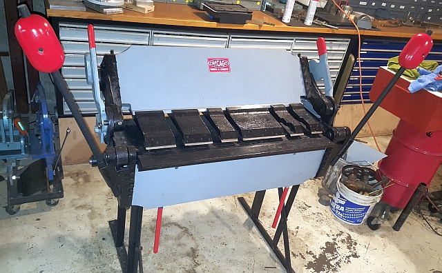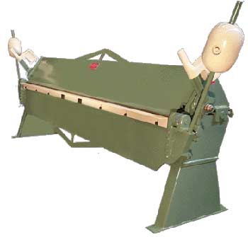
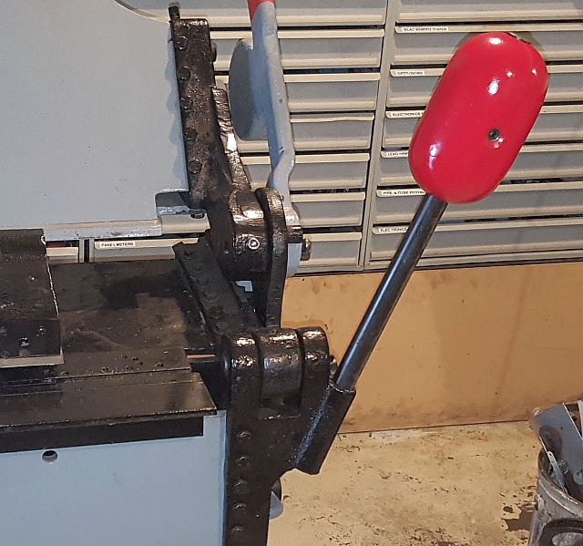
I'm proud of my vintage Chicago box & pan brake made by Dreis & Krump. I don't know how old it is, but one of the castings has "5 32" so it may have been poured in May of 1932. At any rate, it's quite elderly. When it came to me it was missing its counterweights. To me, sheet metal brakes simply have to have counterweights in order to look right, let alone to ease the job of bending. Here is a much newer larger machine from the same manufacturer so you can see what the weights are supposed to look like:
Clearly my machine had to have a pair of counterweights. I could have filled a couple of large tin cans with concrete and painted them red. But I wanted something a bit more sophisticated. I didn't really consider designing and making patterns and having a pair cast, probably because it isn't something I have done before. I really wanted the rounded end look of the factory-made castings. I did consider trying to find a matching pair of old iron cannonballs. Such are available but the prices are prohibitive, to say the least. At any rate, this article is about how I went about designing and building my own.
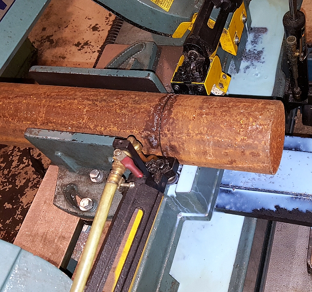
In order to design a pair of counterweights, I had to understand how they work. A guy told me they should be adjusted so that the bending apron just balances in the horizontal position. I don't know if that's how they all work, but it sounded reasonable so that's what my goal became. So first I needed to understand how much torque my weights needed to provide. I was able to measure the weight of the bending apron in the horizontal position, 24" away from the center of rotation. It weighed about 21 pounds. Here's the setup:
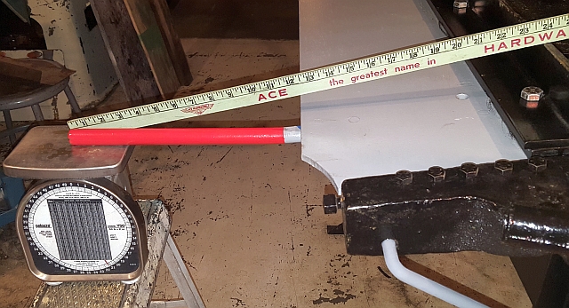
To check my reading, I put 21 pounds of weight into a bucket and adjusted the moment arm (moved it in and out on the piece of pipe) until the bending apron balanced.
Sure enough, it was about 24". So now I knew I needed about 42 foot-pounds of torque. I could make a single 42 pound weight at 12", one 21 pound weight at 24" and so on. Because my shop has limited floor space and I wanted to keep the footprint increase to a minimum, I chose to make two 11 pound weights to be mounted about 12" from the center of rotation.
With that goal in mind, I started working with what I had. I try to use available materials to save money. My buddy provided me with some 4" hot rolled steel round bar, so I started by cutting off a six inch length.
Next I knocked most of the rust off with a cup-type wire wheel on an angle grinder. There are less violent ways to remove rust, but this way was quick so that's what I did. Then it was on to the lathe to make the central hole. I used a sharp 1" drill to drill right through lengthwise:
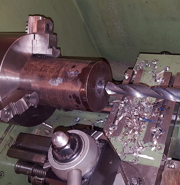
I'd planned to use 1" steel round bar to mount the weights. The pieces I had on hand wouldn't fit through a 1" hole, so I ground up a little toolbit and used a boring bar to enlarge the hole until I got a "rattle fit". Didn't want the weights to bind at all. Then I cut the part into two 3" lengths. A 3" piece of round steel 4" diameter weighs pretty close to 21 pounds, so I was getting closer.
The next step was drilling a 27/64" hole in preparation for tapping 1/2-13.
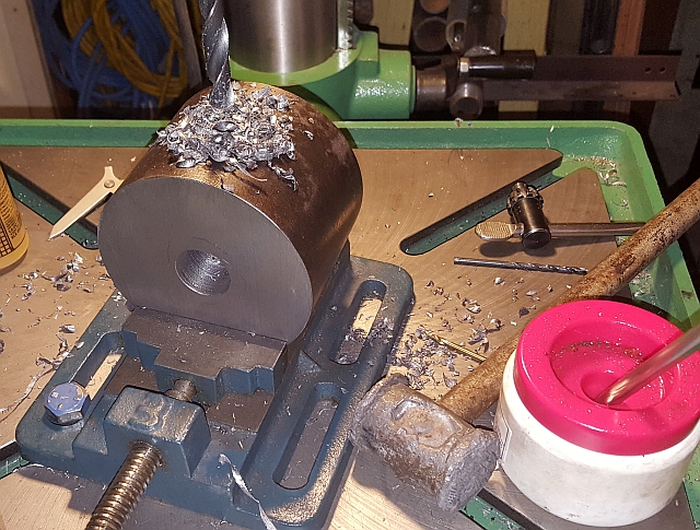
After drilling and tapping, I used a larger bit to counterbore around the hole. My setup wasn't rigid enough, so I got a lot of chatter. But I pretty much got the right look.
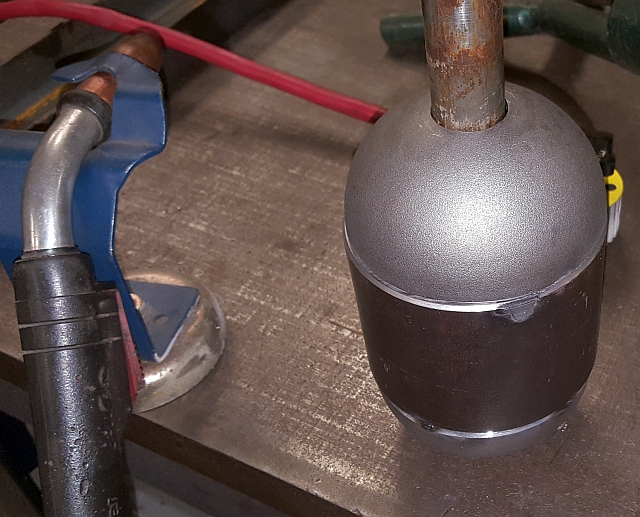
To add the rounded ends, I purchased 4 hemispherical tube ends. These are formed from 1/8" steel and are nicely made. Sadly, they didn't measure 4" wide. They were "pretty close", though, about a sixteenth under. With the old shipyard maxim "we ain't building a Swiss watch" in mind, I went ahead. The half-dome ends come with a 1/8" hole, and of course I needed them bored for a clearance fit on a 1" bar. I thought about various ways to make such a hole. In the end, I decided to temporarily tack them to one of my weights and then bore the hole in the lathe. Here is my setup for tacking an end piece to one of the weights:
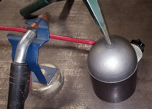
In the image above, you can see part of my "mosquito clamp". I use that quite a bit on the welding table. It worked perfectly for this task. I really like the little magnetic ground clamp. I brought that home from a trip during which we visited a county fair in Iowa and I ran into a vendor who had a show special price, couldn't resist.
Anyway, with the end piece tacked to the round weight it was easy to enlarge the central hole from 1/8" to a comfortable clearance for a 1" hole. I think I bored them to 1.050". Then I cut the tacks using a thin cutoff disk in an angle grinder and removed the ends. The round weights then went back in the lathe where I turned a 1/8" bevel in preparation for welding. I also beveled the end pieces. The next picture shows how I checked the fitting for concentricity before welding.
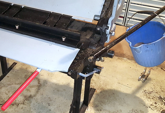
Then I welded the ends onto the weights. With the parts beveled, the welds penetrated the full depth of the end cap material so it was safe to sand the welds smooth. I used a 2x72" belt grinder to sand off the welds and to roughly contour the weights for a smooth transition. I finished with a flap wheel. Then I gave the counterweights a coat of primer, then a bright red top coat. As you can see in the images below, the end result is a pretty good facsimile of the factory weights, scaled to my machine. Note, in the pics below, I hadn't yet made the final counterweight bars. I didn't have enough 1" round bar stock over the weekend. I'll update this page when I get the final mounting bars made.
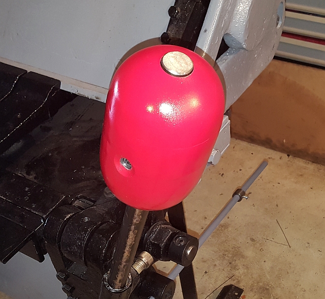
Here's one final shot with both weights installed. They needed to be a bit farther from the center of rotation than I'd figured, glad I put in some extra bar length. Thanks for reading!