Why do I call this the last camelback restoration? I have two reasons. This drill press is the culmination of many design changes over nearly a century of industrial history. Royersford manufactured this model well into the 1980s, but no design modifications were made after the 1960s. So this machine was one of the last production runs building camelback drill presses. Thus I can call it the last camelback. Also, this is my third major camelback drill press restoration. It is a lot of work to restore one of these machines, and it is definitely not a money making proposition. I'm getting on into my 70s now, and I feel confident when I say that for me, in my shop, I won't be restoring any more of these. Thus on a personal level this is my last camelback.
As I mentioned, I'd restored two camelback drill presses before this one. I think I'd become familiar with most of the issues that come up. For example, most of these machines when acquired are missing the flat belts, or the flat belts are there but disintegrating and unusable. Of course, industrial America ran on flat belts for a very long time. Most cities had a vendor who specialized in flat leather belts. But eventually most of these machines were taken out of service and most of the vendors went away. Today you can still buy flat belts but they cost a couple of hundred dollars apiece. So be aware that buying new belts can add quite a bit of cost to a machine restoration. However, at the end of the camelback drill press manufacturing era Royersford had switched over to vee belts. Vee belts are well known and are much cheaper to buy if they need replacing.
Another common issue with old line shaft machines is their shafts generally ran in poured babbitt bearings. My experience is that old babbitt bearings can be worn oblong or have other grievous problems, and these problems can be difficult for a home shop guy to address. Again, Royersford at the end had moved away from babbitt bearings. The model 22 drill press (the one this page was written about) does not have any babbitt bearings. Rather, the shaft bearings were pillow block ball bearings made by Fafnir. So for this drill press, anyway, you're guaranteed not to have to work on babbitt bearings.
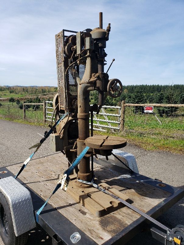
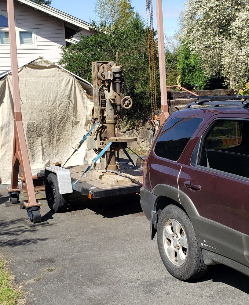
The upshot was that in early 2023 I saw an ad for this drill press and when I realized it had vee belts and ball bearings, I felt compelled to buy it. I had to drive half a state away to get it and bring it home. It was a nice day when I went and got it and I got lots of admiring looks on the way home, so that was a fun trip. The machine was on the expensive side at $250 but it was complete and looked to be in good condition, so I felt it was worth it. Here is a picture of the drill press loaded on my small trailer as I started home:
And here it is in my driveway prior to unloading it off my little flatbed trailer:
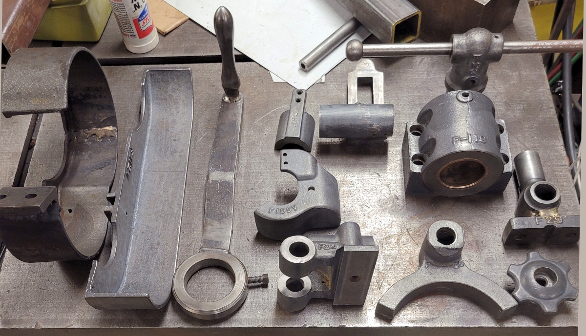
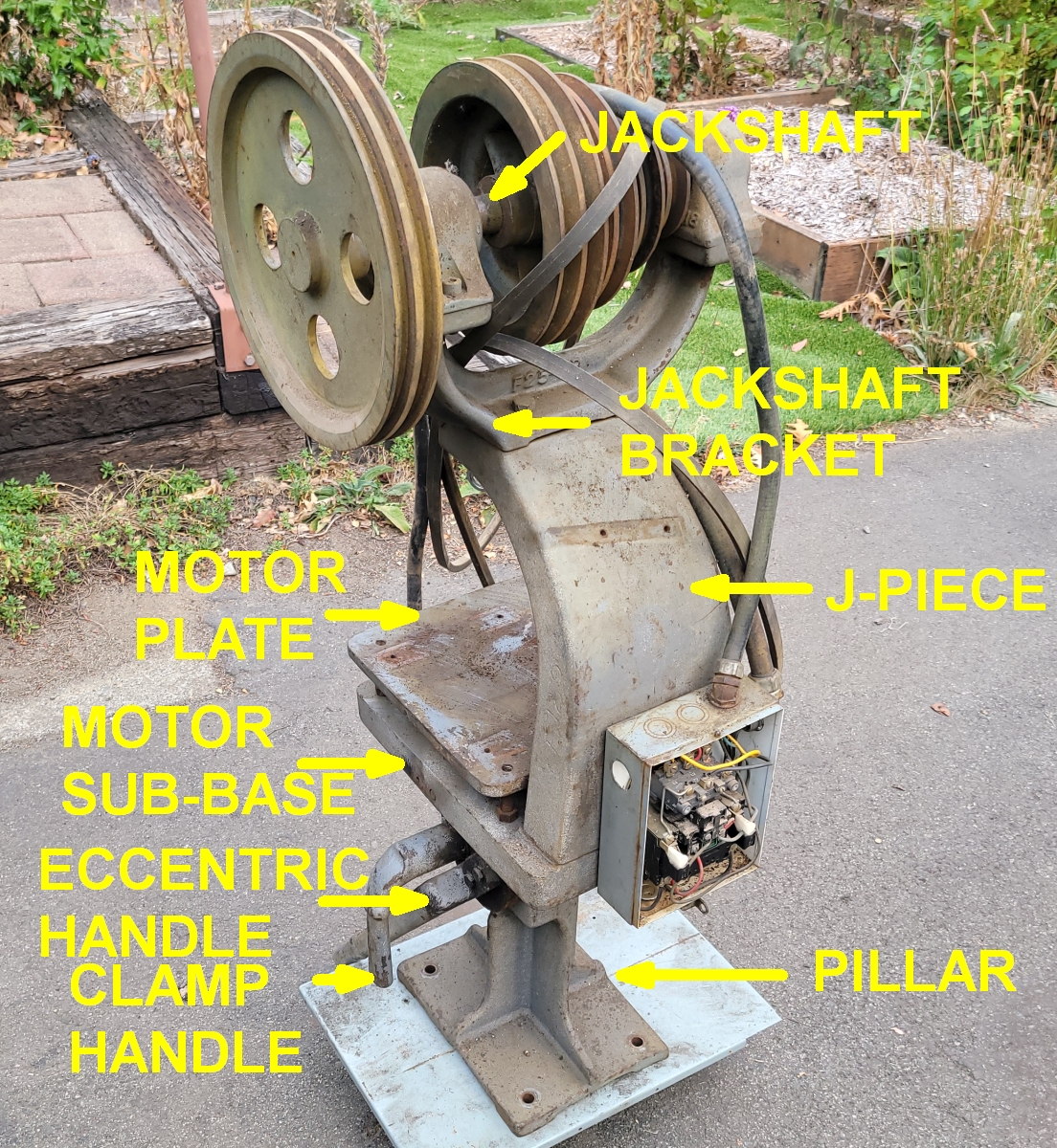
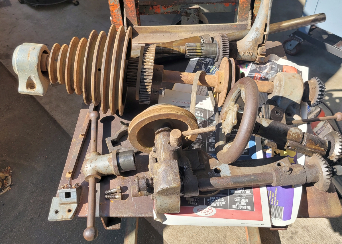
I began the restoration in early September, 2025. I removed the motor assembly which had been bolted to the back of the machine. I called this the "back stack". Here is a picture just after removal. I added names for the various parts:
The back stack is an assembly of iron castings. What I did was to take it all apart. Each individual casting then got the same treatment. I started by going over it with a pneumatic needle gun (an I-R Model 125) which removed nearly all of the old paint. Then the casting went through an electrolytic derusting bath, usually for 12 to 22 hours. The casting was removed from the bath and taken straight outside to the shop driveway where it was pressure washed. After that, all the paint and rust had been removed and all that was left was soaking wet bare iron casting. I blew each casting dry and then sprayed it with a water displacer/rust preventer called CRC 3-36. Then each casting was set aside to dry at which point it was ready to paint. Here is a pile of castings from the back stack all cleaned and ready for paint:
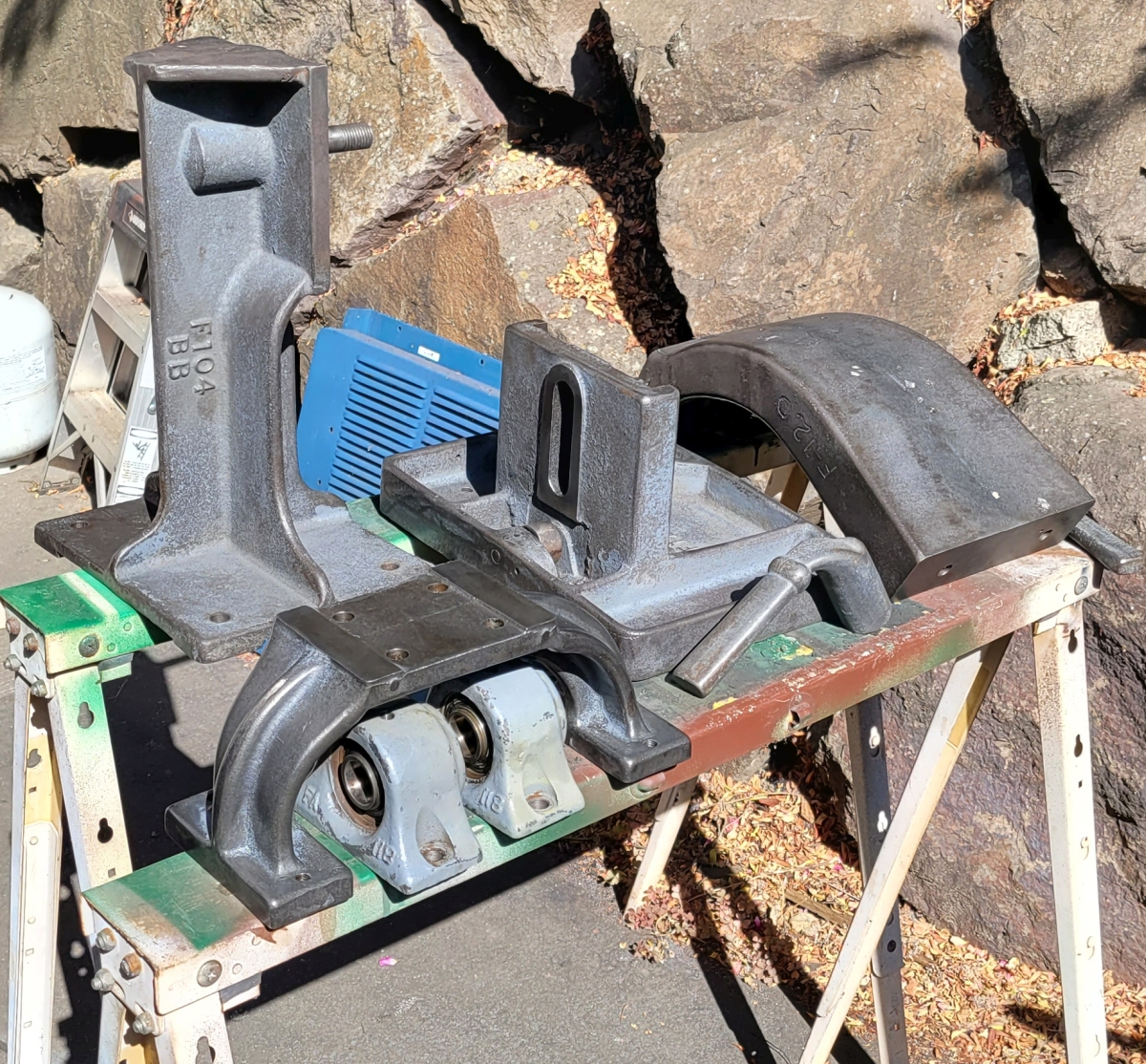
Actually, the pillow bearings shown just above didn't get that same treatment because I wasn't quite sure about putting them into a derusting bath. The rest of the castings got painted, though. I used a Benjamin Moore DTM (direct to metal) paint in a dark green color I like, applied with a paint brush. Unless it's with a rattle can, I'm no spray painter. Here's an image of the back stack starting back together after painting:
One of the appealing aspects of camelback drill presses is their simplicity. They are put together from subassemblies like the back stack. I did this restoration work on one subassembly at a time, putting each one back together afterwards. This kept my shop from being overrun with parts, and also it's good to put something back together while you still remember how it goes together. Of course, I took lots of pictures so if I got confused I could go look at how an assembly looked before I took it apart.
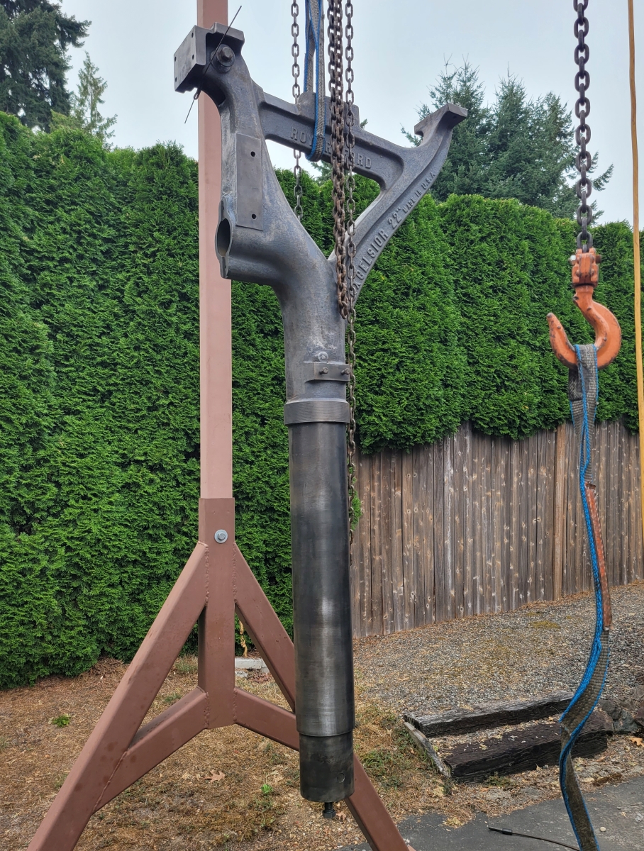
The overall game plan was to get the frame stripped and find a period of nice weather where I could work on the bare frame and base outside under the gantry. Assembled, this machine weighs over 1400 pounds. Many of the pieces are far too heavy for one old guy like me to lift, so I need the overhead hook to help with that. Anyway, here is the pile of as-delivered subassemblies prior to cleaning and painting:
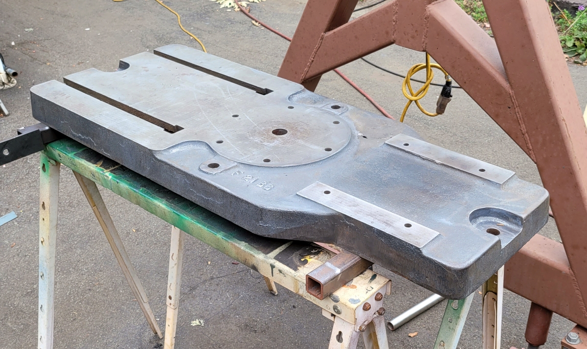
With the subassemblies removed I took the frame and base outside. Here you can see the base removed from the frame and set up on sawhorses. The frame is sitting lightly on a block of wood next to it with the table support casting still installed on the column.

Just as I do with smaller castings, I start work on the frame by going over it with a needle gun. Old paint just flies off when you hit it with a needle gun. If you use a wire brush, it will not come off as well, plus a lot of the paint comes off as fine dust which spreads all over the work area and makes the operator wear a dust mask. I'm a big fan of the pneumatic needle gun. Anyway, with the paint mostly gone you can see how clear and sharp the lettering is. Royersford's people were highly skilled at casting iron.
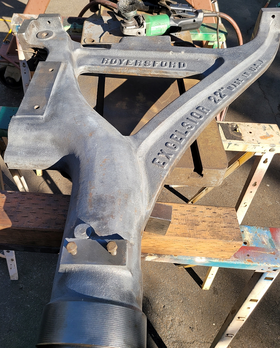
After needle gunning the drill press body, I went over it with a wire wheel mounted on an angle grinder. After needle gunning it's very easy to get the rest with a wire wheel. I cleaned the column using shop cloth shoeshine boy style. It doesn't look like chrome but it doesn't look rusty anymore and I like the industrial patina left by the hand polishing.
The next three pictures show the base casting, the column foot casting and the table support casting after cleaning. At this point a lot of guys spread on body putty to make everything look smooth. I have never done this. I don't mind the raw casting look.
Sometimes when casting the iron gets holes in it. This is called shrinkage porosity. The drill press base had one of those. It had been filled with epoxy putty. I consider a defect like this to be ugly so I mixed up some J.B. Weld and filled the gaps. After sanding and painting it is no longer visible.
I don't have any pictures of parts being painted. I'm assuming you know what a can of paint and a paint brush look like. Anyway, I painted the 4 large castings, then let them dry for a couple days in the late summer sun. After that the paint was dry to the touch but not yet fully hard. But I could put these 4 parts back together, put the resulting assembly back on the cart and roll it under cover. Seattle has been known to get rain even during Indian summer.
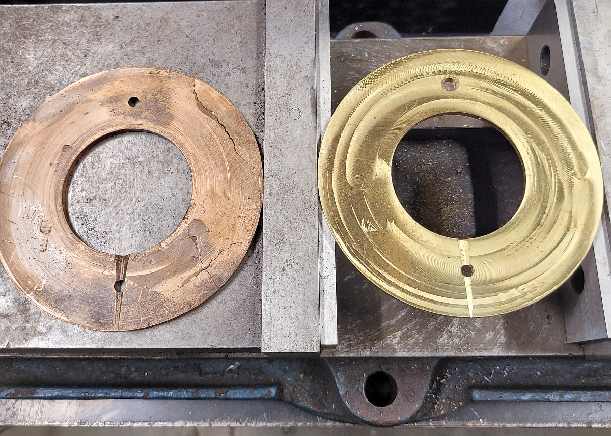
As I removed the crown gear (the large bevel gear on top of the spindle) I saw that the drill press had been fitted with a flat bronze thrust bearing in the shape of a big washer. Mine was not in usable condition. It was cracked in several places and heavily scored in others. This piece is critical to the function of the drill press. The crown gear sits on this thrust bearing, so it is obvious that the crown gear is located up and down by the thickness of the bearing bronze. If the crown gear is too low or too high the backlash between the two bevel gears is incorrect and the result is a lot of noise and excessive wear on the gear teeth. I had a suitable chunk of brass which my friend Andy volunteered to mill to size and thickness with his CNC mill. I was able to match the thickness within 0.002" and was able to match the oil hole with its groove and the hole which sits over a pin to keep the thrust bearing from spinning. It was quite a bit of work to get this part right but it was worth it to hear how quiet the crown gears are when the machine is running. Here you can see the old and new bearings side by side. The tool marks on the new bearing have very little depth and in use the thrust bearing will soon be smooth and shiny.
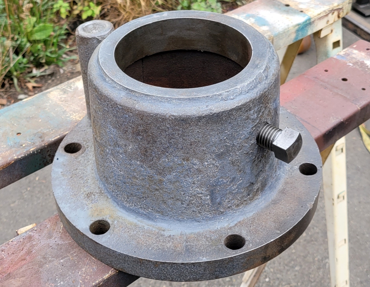
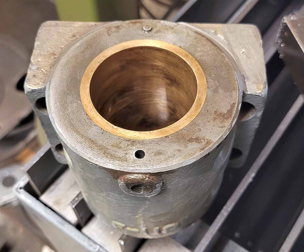
Pillow blocks can have ball bearings in them or they can be plain bronze bearings. At the top of my spindle is one of the plain bronze ones. This picture shows it from the top. Note the antirotation pin. The threaded hole visible in the picture holds a 1/8" pipe threaded fitting with a GITS oiler on it, the kind that is adjustable so you can control the number of drips per minute when it's running.
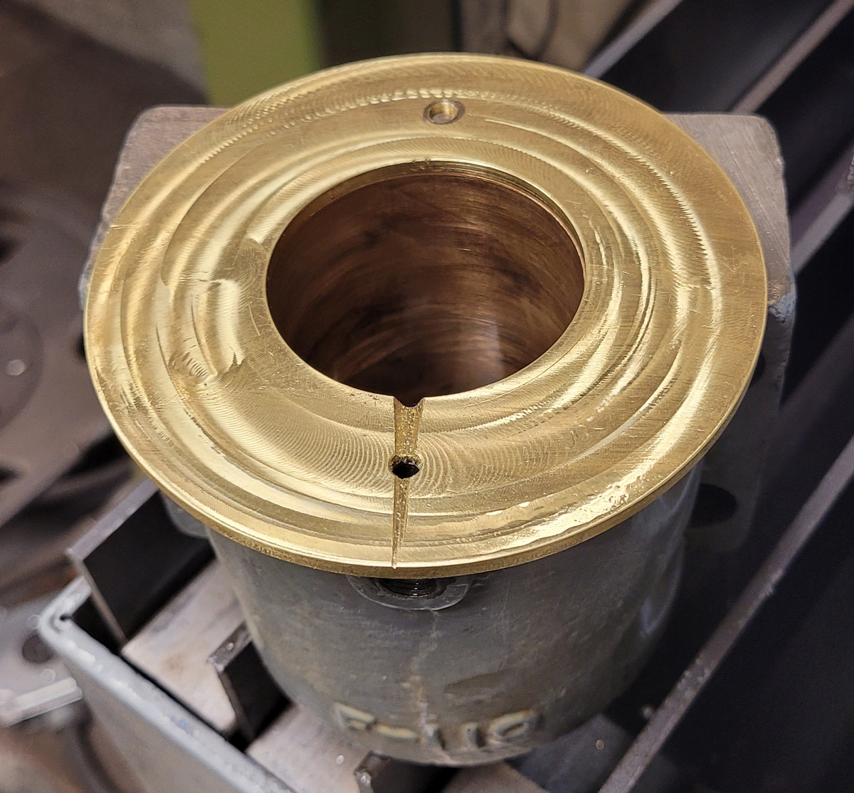
The thrust bearing sits directly on top of that pillow block. You can see how it fits over the antirotation pin.
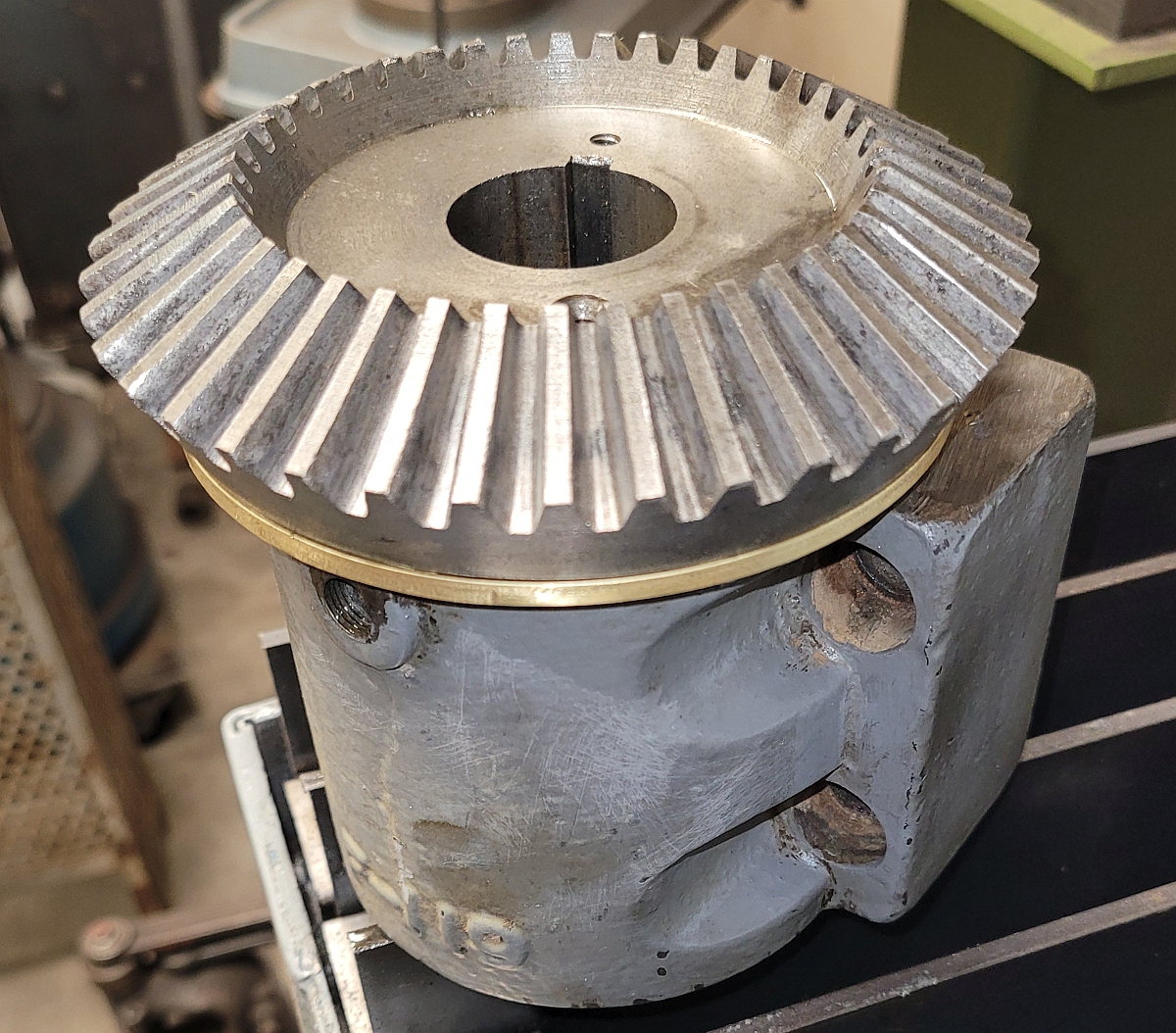
The crown gear goes right on top of the thrust bearing. You can see the keyway in the next picture:
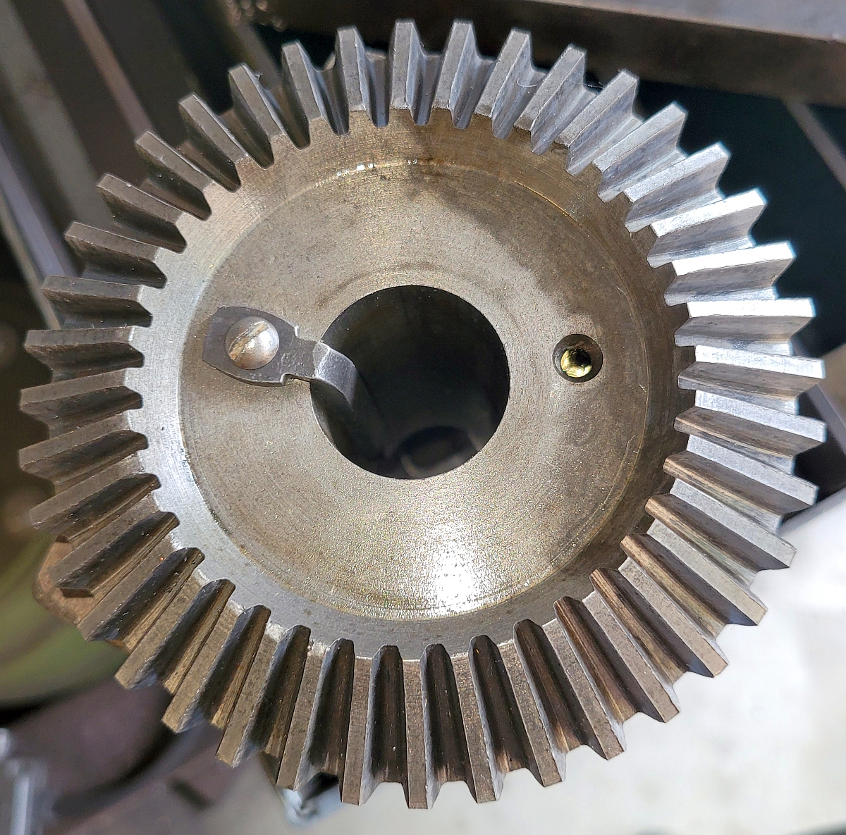
The spindle has a keyway. As the drill press is operated the spindle shaft goes up and down. In order that the key doesn't move, it is secured to the crown gear in what I think is a very clever way.
The pulley on my jackshaft (the intermediate shaft between the motor and the top shaft) had been dropped and one of the flanges was broken out but still barely attached. My friend Ernie vee ground the cracks and heated the pulley to 650�F and brazed the piece back on. Then I machined the brazed area. It no longer looks new but a braze repair on cast iron is strong and as long as nothing gets dropped on it it should last forever. It's also not the only broken and brazed thing on this machine. Anyway, this is what it looked like when I was done machining.
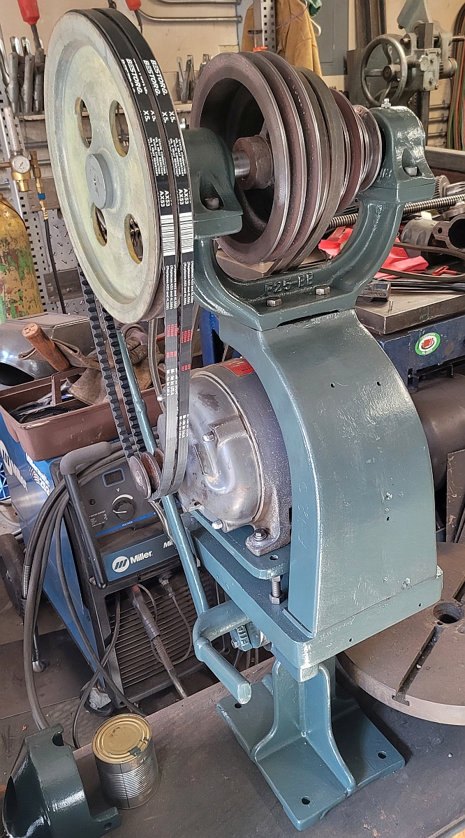
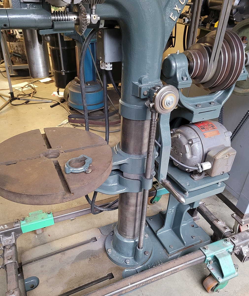
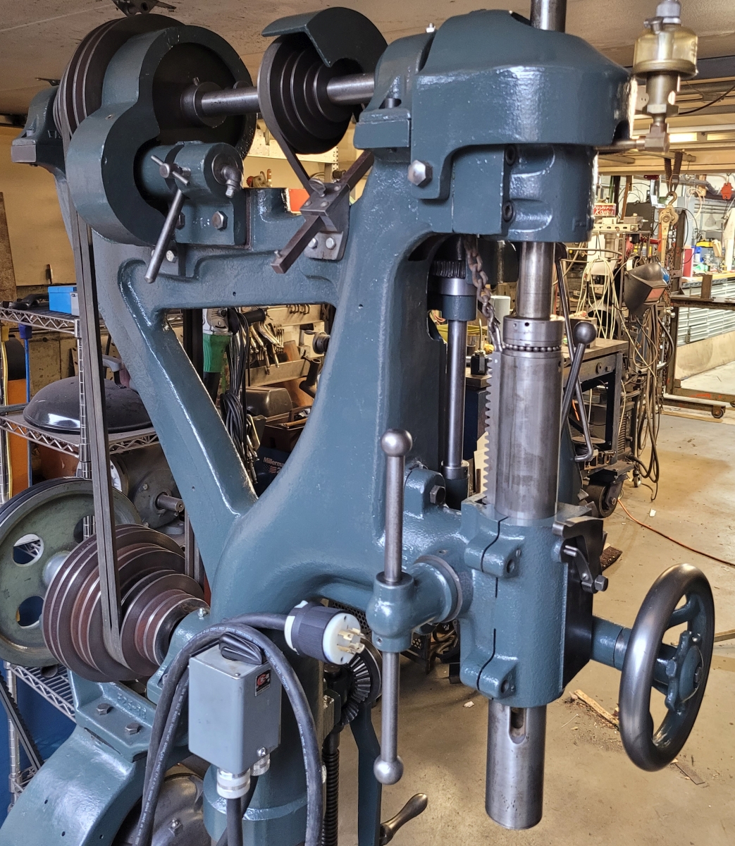
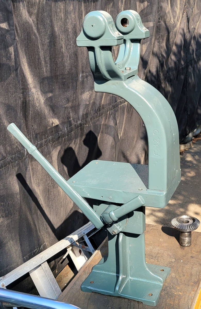
With the pulley repaired I put the back stack together again. Consider the difference between flat belts and vee belts. Flat belts can easily be shifted sideways on a multi-step sheave without detensioning. Vee belts can not. To shift vee belts you have to loosen the belts, that is move the pulleys towards each other. That is one big difference between the model 22 drill press and its predecessors. If you look at the next picture you will see two handles, a short one and a long one. The short one is a clamp nut. When you loosen it then the long handle can move. The long handle is attached to an eccentric which bears on the motor plate. By moving the long handle you can lift the entire middle part of the back stack, releasing tension on the drive belts above the back stack. The motor belts (not tensioned in this picture) are not affected.
After I finished the crown gear, I moved to painting. Here you can see a nice pile of very cool Royersford castings ready to paint. If you look closely you can see more braze repairs. As long as the guy doing the brazing knows what he's doing those repairs will hold up forever.
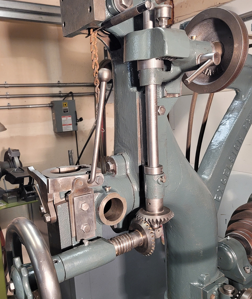
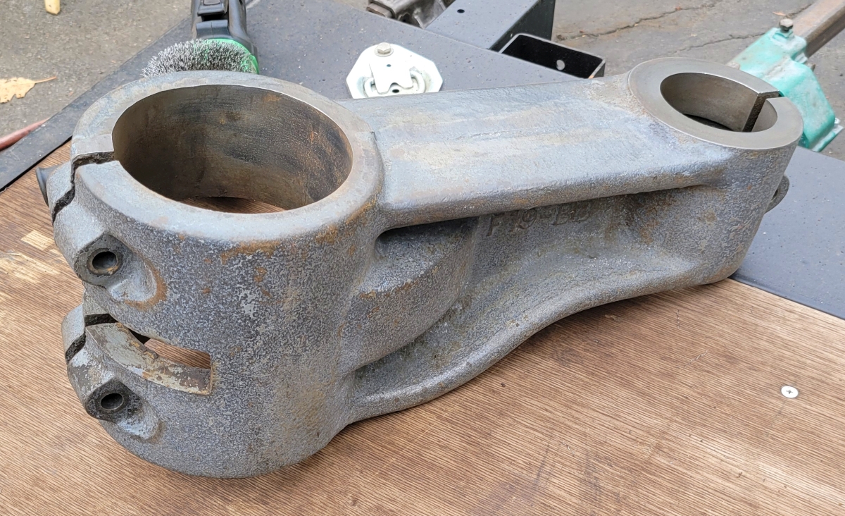
Earlier I wrote that the gears on this machine were all in good shape. There is one exception. Here is a picture of the power downfeed mechanism on this machine:
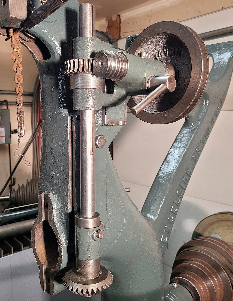
The upper part of the feed has a worm/worm wheel setup which provides a 30:1 reduction in speed while changing the direction of transmitted motion 90 degrees. There is a cover over that bit in the picture I just showed you. This picture shows that worm and worm wheel without the cover.
As you can see, the worm shaft is connected to a vee belt pulley which is belted to another pulley on the top shaft of the machine. As long as this belt is installed, whenever the top shaft is turning, the worm shaft turns also. The preferred way to lubricate a worm/worm wheel is to run it in an oil bath. With the gears oriented as they are here, that is not possible. The cover that goes over the worm has a grease cup fitted. In use you are supposed to give the top of the grease cup a twist every so often and add some grease which will hopefully reach the worm and worm wheel. Sadly, this is not a great lubrication scheme and in fact my worm and worm wheel were quite worn. I spent a lot of time and effort learning all about worm gears and finally decided I could not make new gears. I asked my friend Joshua about it and he chuckled and pointed out my gears are only worn on one side of the gear teeth, since the top shaft always spins in the same direction. So I simply machined the gears and made some spacers and wound up turning the gears around 180 degrees. Now everything turns the same direction but the force is transmitted by the unworn side of the gear teeth. I was very relieved to find that this approach works perfectly.
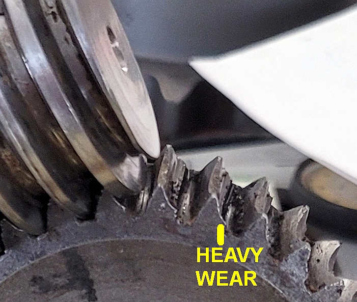
I thought I'd include a shot showing the pronounced wear on the worm wheel teeth, clearly evident in the following image:
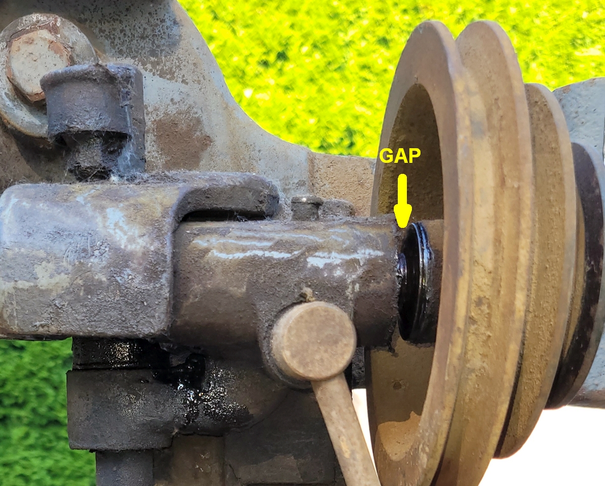
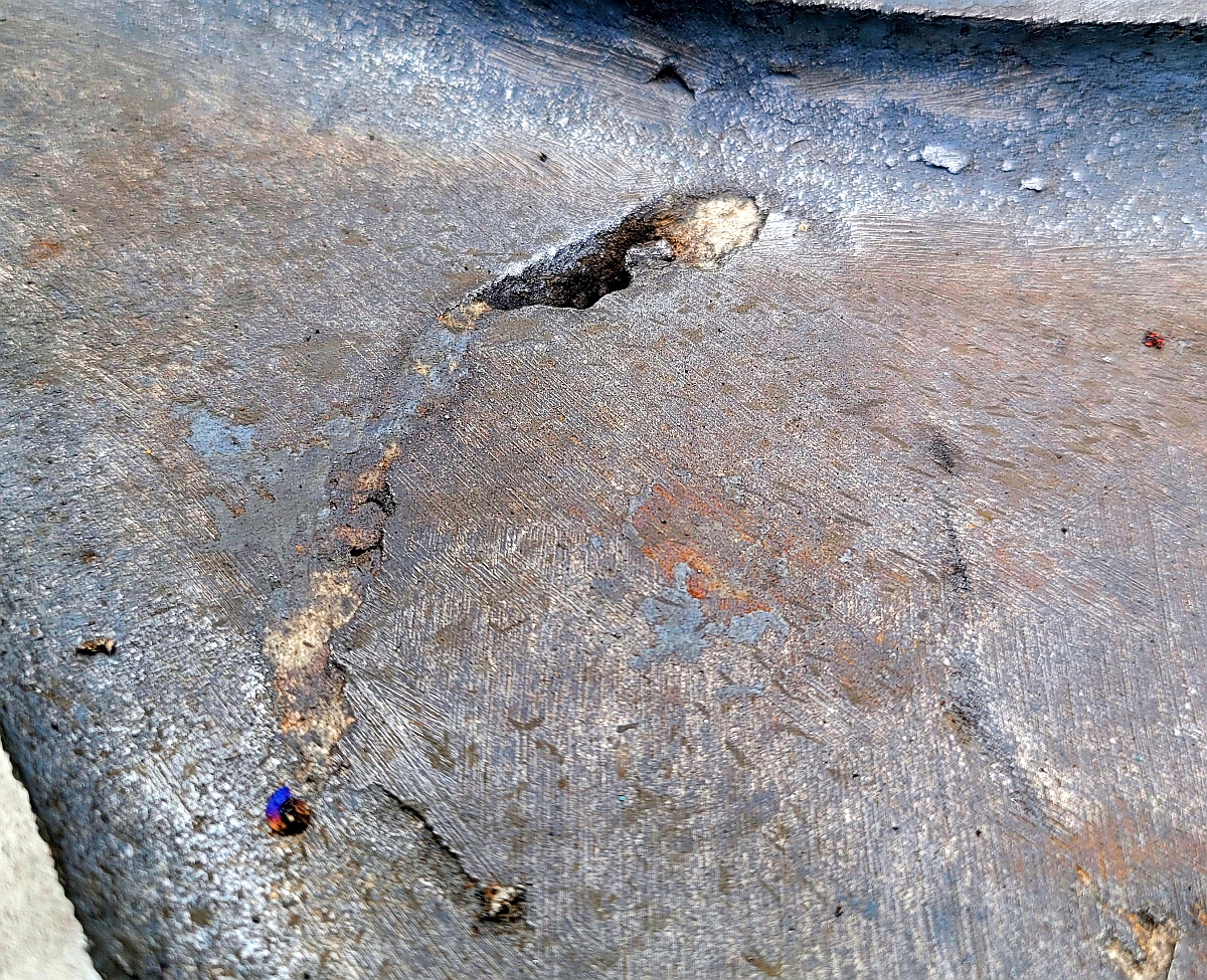
Notice that the right sides of the teeth on the worm wheel are badly worn. However, the left sides of those teeth are still straight and unworn. Turning the gear around did the trick. There was another problem in the same worm area. Aa a worm turns it tries to move its shaft along its axis, like screwing in a bolt. Good design uses thrust bearings to resist that pull and restrain the shaft from moving. When I took this apart, there was no thrust bearing. The pulley had been forced to run hard against the cast bracket and both the pulley and bracket had worn away to a very considerable degree. See:
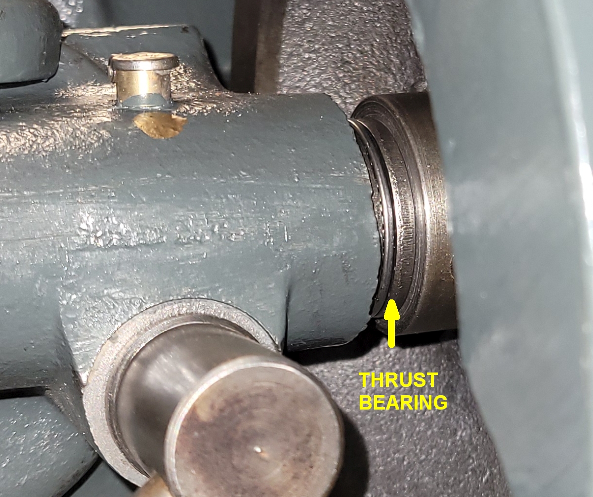
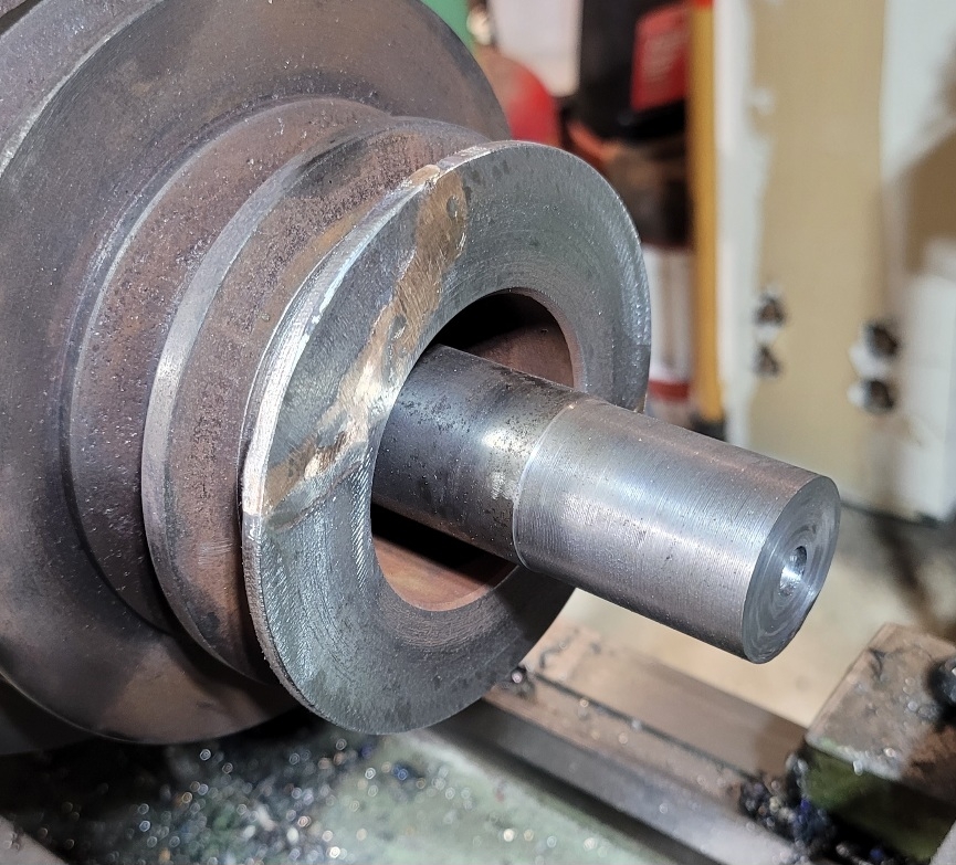
As is obvious, this shot was taken before anything was cleaned or painted. My solution was to buy a new roller thrust bearing and two hardened washers. Together their thickness just about filled the wear gap shown in the image above. I forgot to take a picture of the worm gear during assembly, so I took one after everything went together.
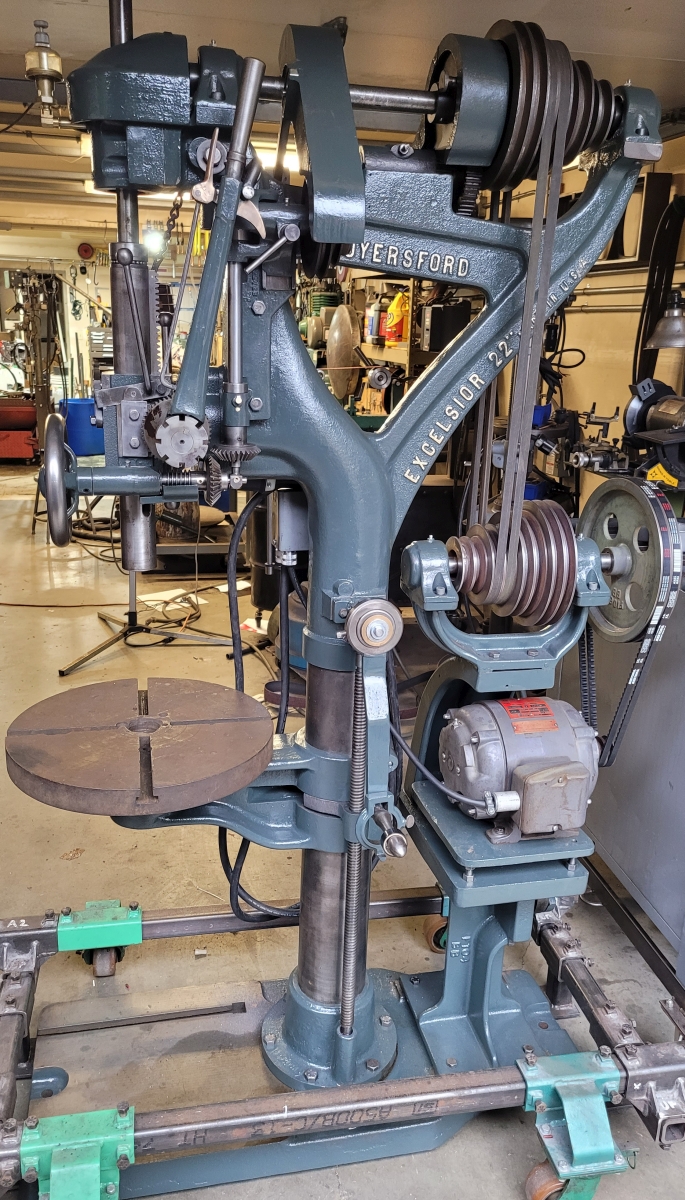
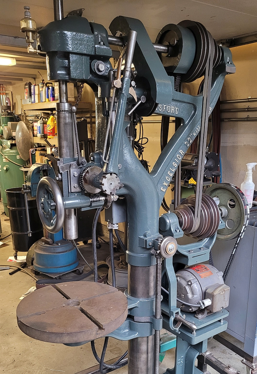
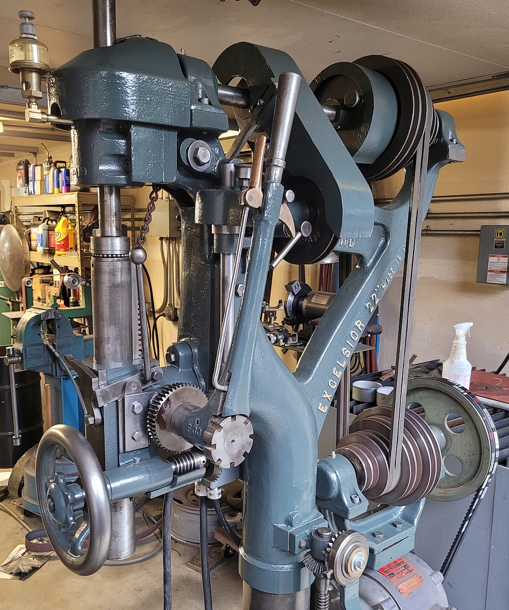
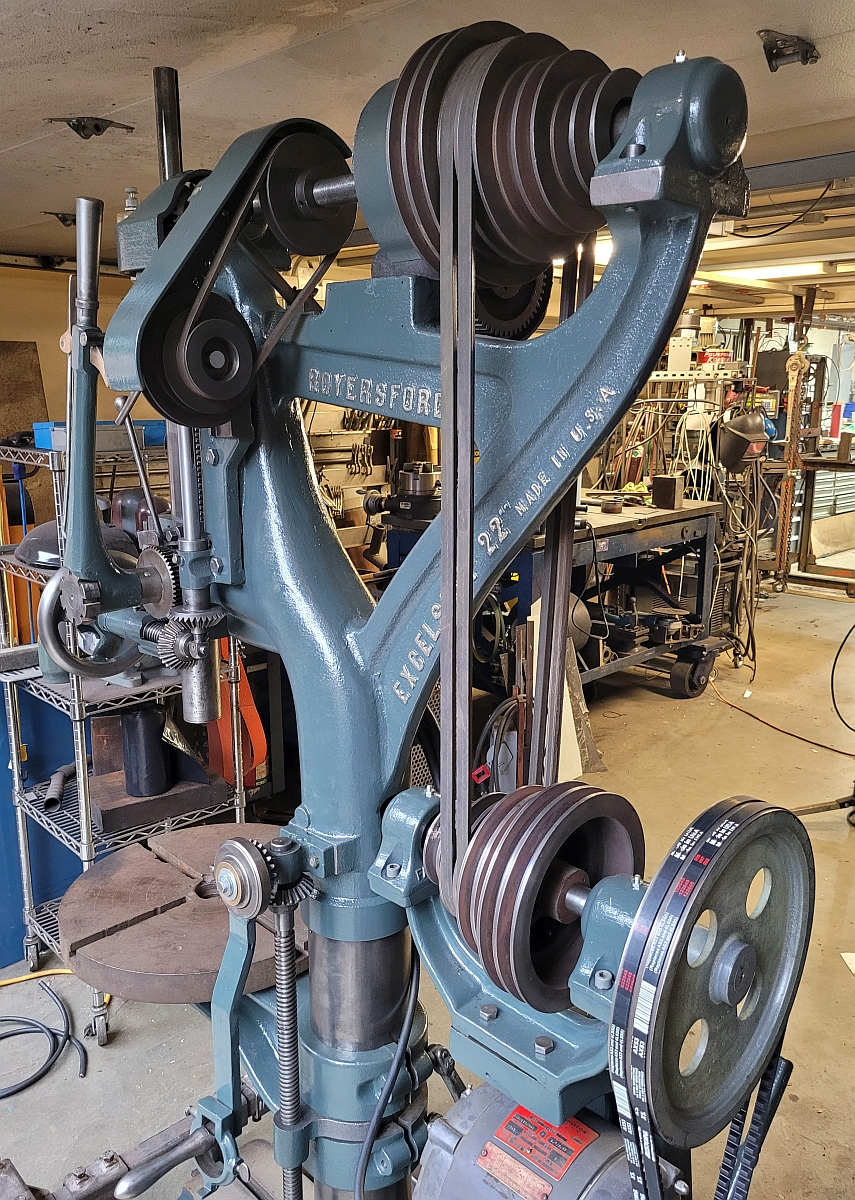
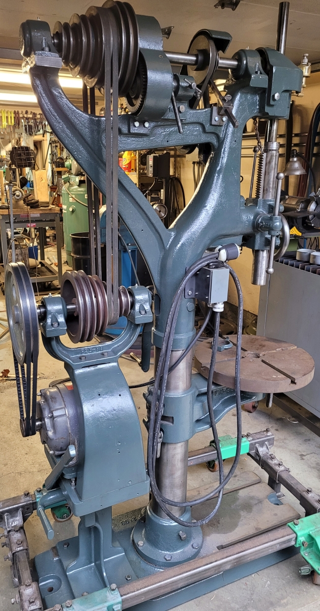
Everything went surprisingly quickly after I solved my power feed problems. Here are a few pictures of the machine after the restoration was complete. Well, it's not *quite* complete - I haven't done a thing to the drill press table yet. I'll scrub the dirt and rust off of it and might fill some overdrill marks with metal bearing epoxy, don't know yet. It's fully functional as is. Anyway, here goes, enjoy!
Thanks for reading!