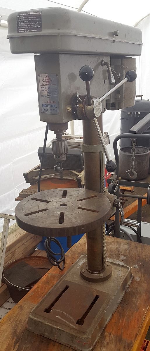
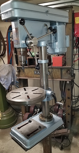
This describes a 14" drill press made in Taiwan in the 1980s, restored and updated to today's standards. Improvements include replacing the original AC motor with a DC permanent magnet motor. Above you see two pictures. The one on the left is what it looked like when I bought it (for $40) in 2017. The one on the right is what it looked like after I did a first-cut restoration but before the DC conversion.
Many of the steps involved in disassembling a drill press can be seen in a good video produced by eReplacementParts:
Rather than going step by step through the initial restoration (prior to the DC conversion) I will summarize. The rebuild consisted of:
complete teardown of the drill press
derusting and polishing of the machined surfaces of the table and base
cleaning and polishing the column
polishing the 3 handles and the horizontal feed shaft
replacing bearings in the head including spindle and pulley bearings
cleaning and repainting all painted surfaces
replacing a damaged work light fixture
replacing the entire wiring harness inside the head
new power cord and AC plug
clean and inspect all fasteners replacing with new as needed
built a floor stand for the drill press
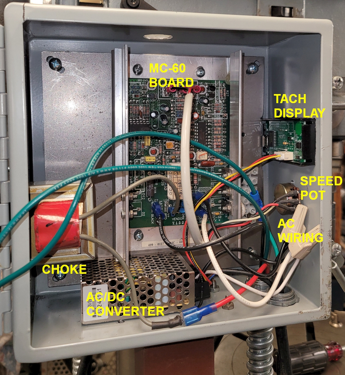
I've restored drill presses like this several times. This time, I opted to change the motor to a speed controllable DC permanent magnet motor. I got the control board and choke from a free used treadmill. The better grade of treadmill motors have a rigid base and 5/8" shaft. In fact, many of these will bolt right on where the original 56 frame motor did. However, in the end I decided to use a commercial DC motor because it has a TEFC case. I did not think it was wise to have lots of tiny steel swarf drawn into a motor with permanent magnets in it.
I used a treadmill motor controller called an MC-60 to control the speed. I chose the MC-60 because the speed is controlled by a single speed potentiometer as opposed to needing another module like more complex controllers do. I do recommend using a motor controller which senses the back EMF of the motor and uses that as feedback to keep the motor speed mostly constant under load. The MC-60 and most later motor control boards have this capability.
Given that the drill press's speed is now controlled by a single knob (albeit in conjunction with the belts), it made sense to add a digital tachometer display. The tachometer I chose was about $12 on Amazon and came with a Hall effect sensor which detects a magnet. I will include links to the electronic upgrade parts I purchased from Amazon below.
I mounted all of the control electronics in a sheet metal box. This is what the inside of an early version looked like:
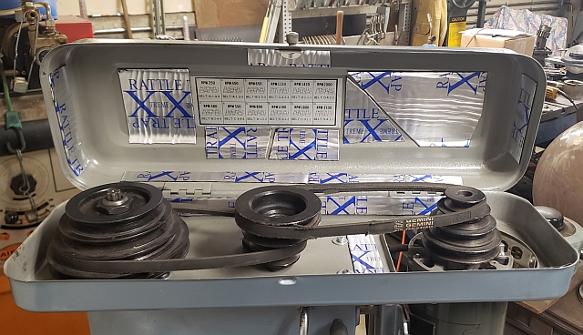
This small version control box is mounted to the top of a riser tube which is welded to the steel floor stand I made for the drill press. You can see it in the next photo. You can also see the tachometer display which reads the RPMs at the chuck.
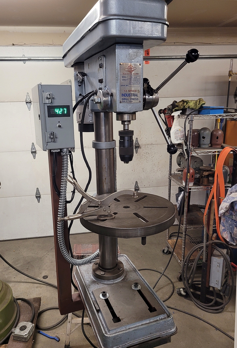
Also in the above picture you can see the undamaged sheet metal belt guard. I do not select old drill presses to restore if this sheet metal is bent or distorted or damaged at all. It's simply too hard to fix. The sheet metal belt guard is often the source of a lot of rattle noises. I had a box of scraps of sound deadening mat left over from a camping van build and I stuck scraps of that material all over the inside of the belt guard to help dampen the vibrations.
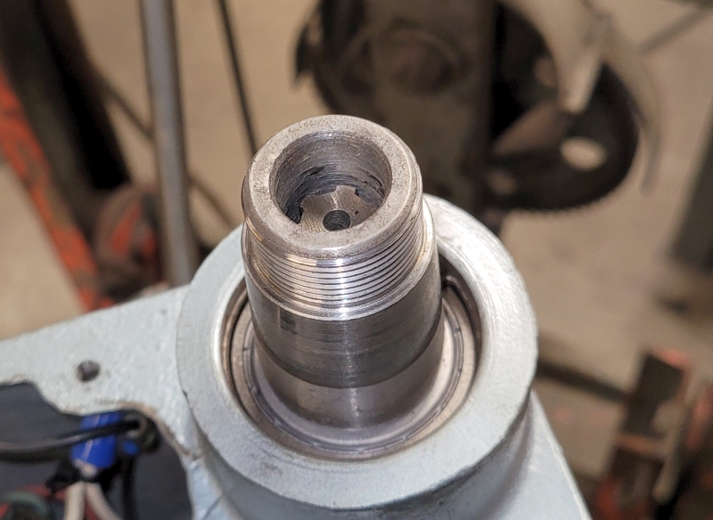
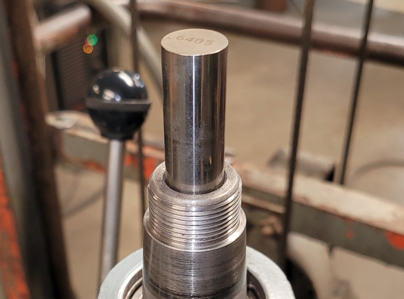
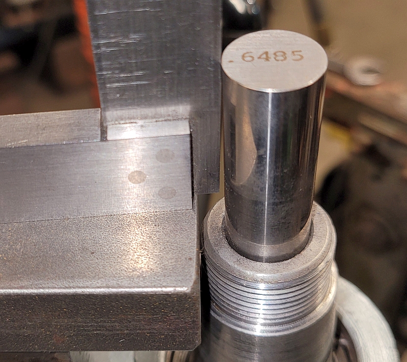
There were a few issues with this machine which I fixed. The idler pulley swivels about a pin in a hole in the drill press head casting. It turns out that hole is not parallel to the spindle. I started by verifying that the idler pulley hole is perpendicular to the top of the head which it turns out is not parallel to the spindle. Here is how I measured that error. First, the spindle is lowered some and locked. This exposes the bore at the top of the spindle.
I put a piece of steel plate on the top of the head casting with a large machinist parallel on the plate. On top of that I placed a rectangular bar which extended to the gage pin, and then I put a small square on top of that rectangular bar. Here is that setup:
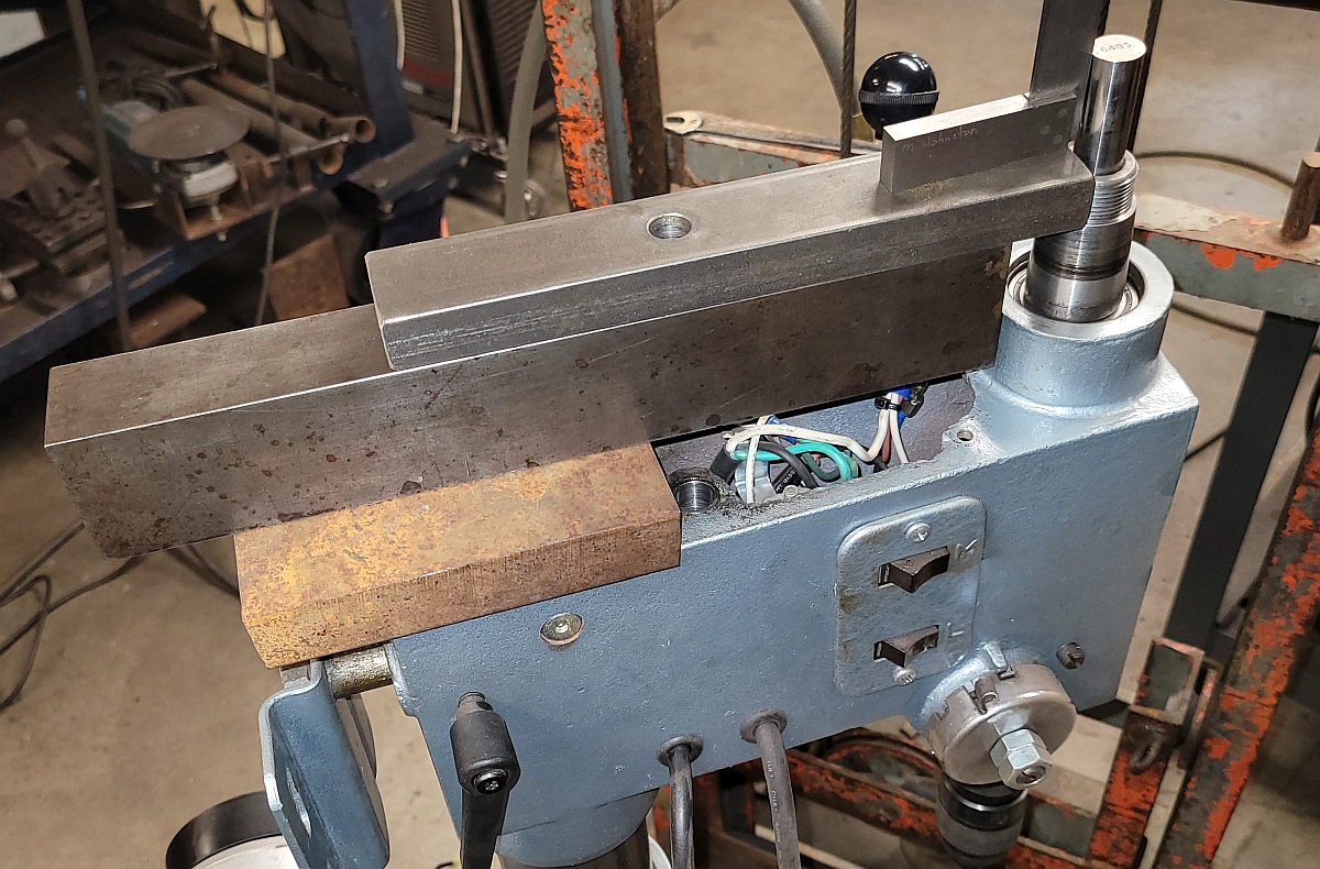
As I'd suspected, the spindle axis as indicated by the gage pin is not square to the top of the drill press head casting. See the gap at the base of the blade on the square:
Next I shimmed the steel plate atop the head until the square indicated the steel plate was perpendicular to the spindle axis. You have to look carefully at the edge of the steel plate to see the shims peeking out.
![]()
With the 1" plate square to the spindle, I clamped it in place and set up a mag drill to true up the idler pulley hole:
![]()
Then I drilled the hole out oversize and used Loctite to fix a bushing in place. The ID of the bushing closely fits the pin on the idler pulley. Now the idler pulley is square to the spindle. You can see that the pulleys line up well.
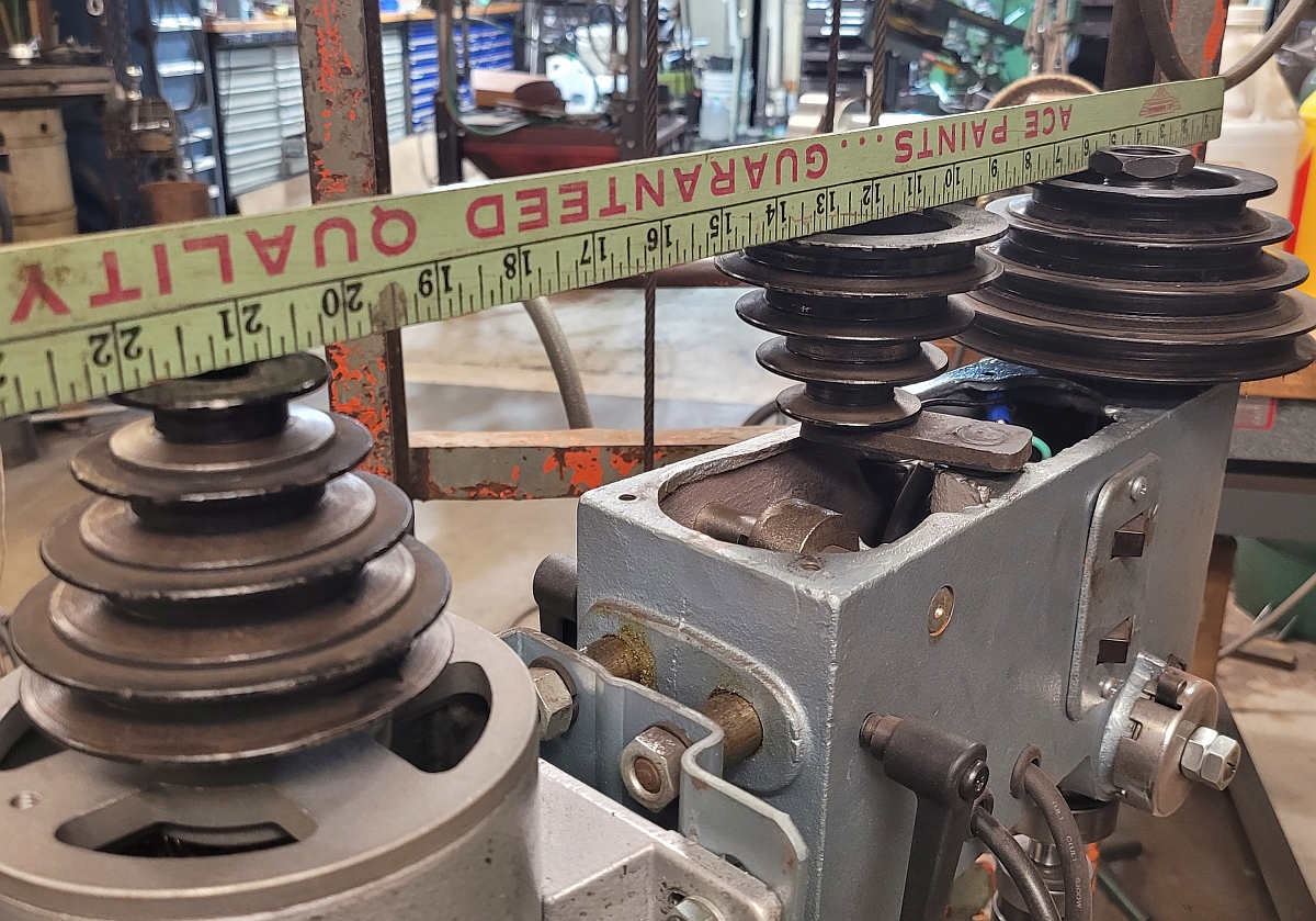
I believe the tilted idler pulley is a common problem among imported drill presses of this era. The result of a tilted pulley is misaligned pulleys which translates to belt flutter i.e. vibration. So this simple repair makes a drill press run more smoothly.
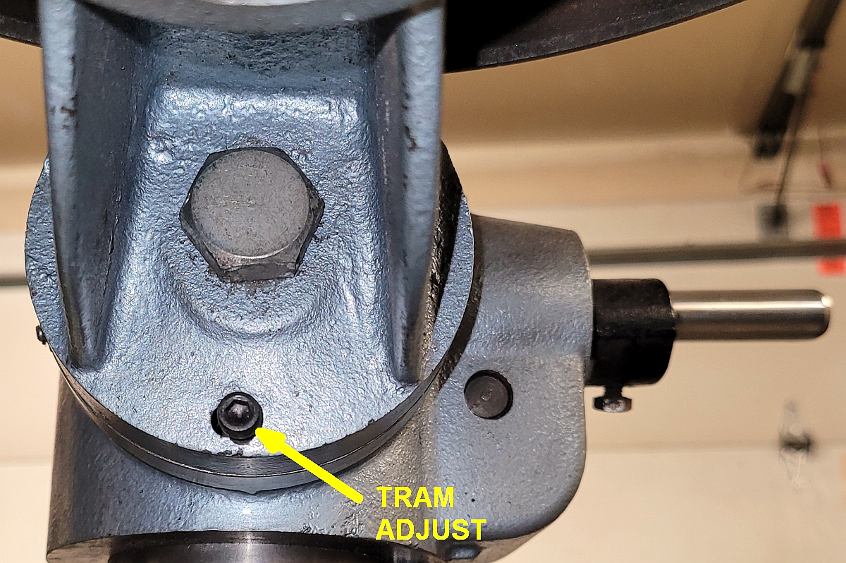
Another problem I've seen on several of these import drill presses is that the tables are out of tram i.e. not square to the spindle axis. These tables can tilt left and right so any error can be adjusted out but there is no way to adjust to tilt up/down. My table was 0.025" low in the front. I could have shimmed the table at the bottom but shims fall out and I decided to drill/tap a hole and install a tram adjust set screw. Now if the front is a little low I can tighten that set screw a little and it will raise the front of the table. It works really well.
Thanks for reading!